© AGRGS 2016 | Data subject to change without notice
67385867493098462 | en, eu, V5, 07. Oct 2016, page 31
Readers are connected to the controller terminals according to Sec. 6.3 Connecting readers and
contactors. Overview.
Reader for OUT records on the first registration board.
Reader for IN records on the first registration board.
Reader for OUT records on the second registration board.
Reader for IN records on the second registration board.
Table 8. Reader assignments when working in Registration Board configuration
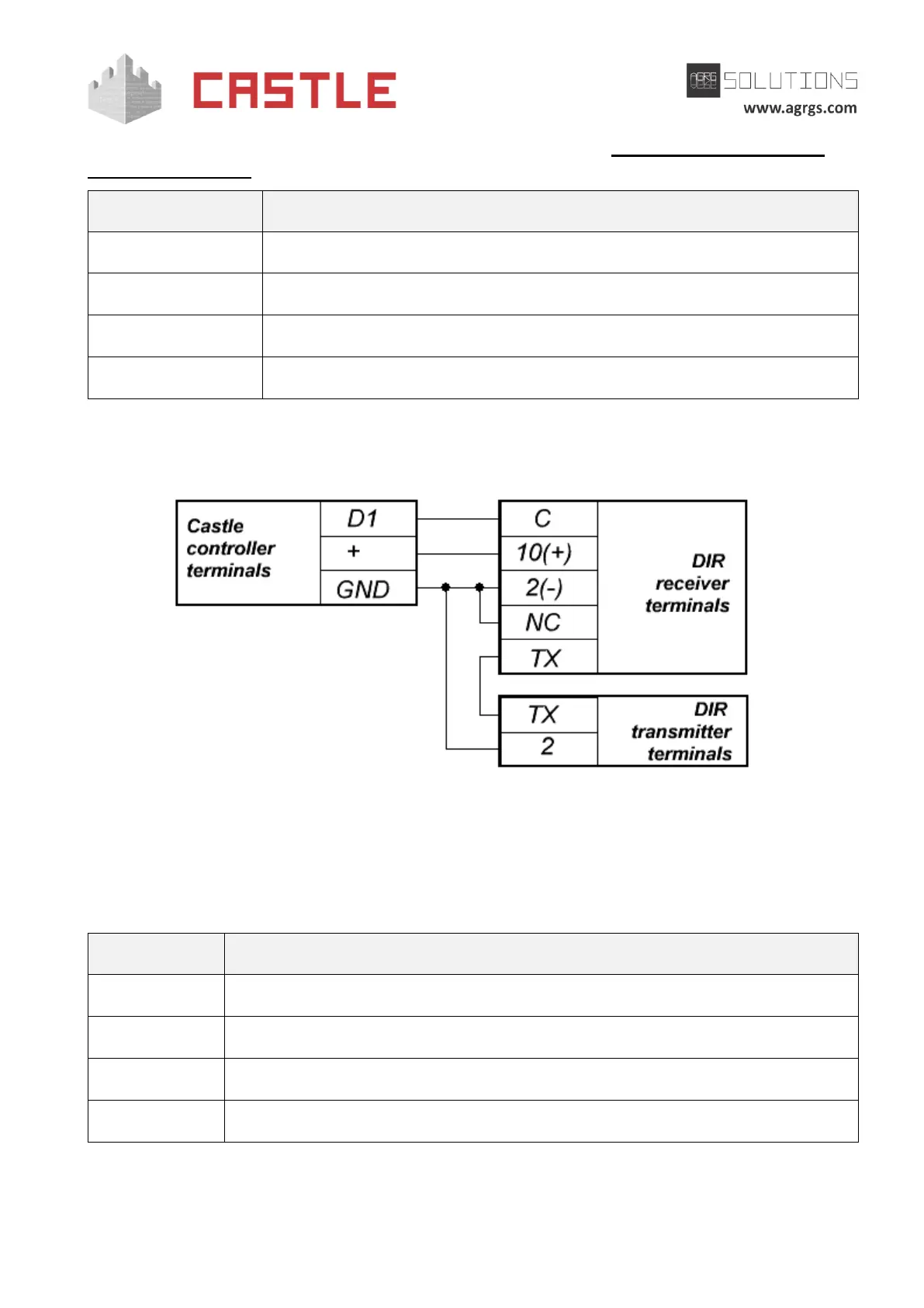
If you need to account passages without digital IDs, connect passage sensors to the controller.
Pic 17. DIR photocell sensor connection example for Registration Board mode
Legend: terminal "+" is + 12V controller power supply.
The DIR photocell sensor should be switched to 12V power supply mode.
The rest of the photocell sensors are connected similarly to D2, D3 and D4 terminals.
Normally closed sensor A of the first registration board
Normally closed sensor B of the first registration board
Normally closed sensor A of the second registration board
Normally closed sensor B of the second registration board
Table 9. Terminal assignments in Registration Board configuration
The distance between beams of the photocell sensors is about 100 to 300 mm.