S0607080K
Page 53
Transmission and Torque Converter
(ZF 4WG-310)
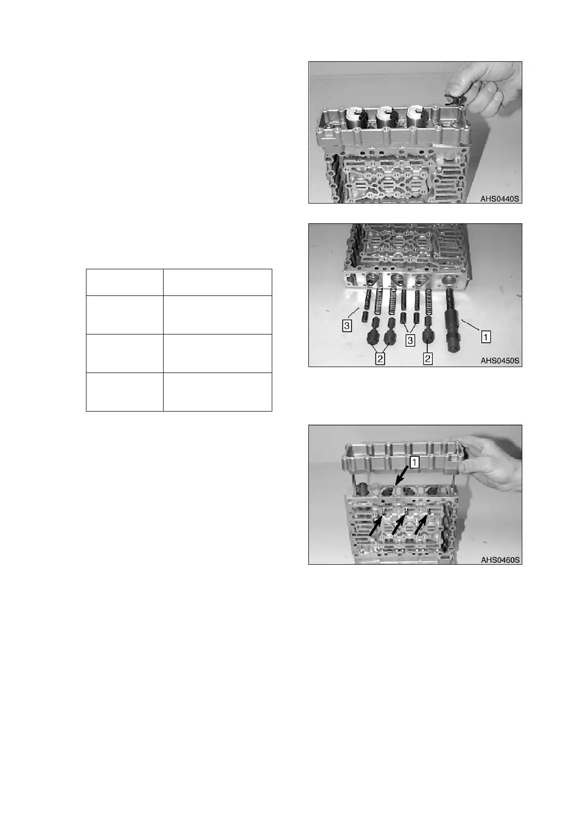
7. Introduce pressure regulators and secure
them using retaining plates and socket
head screws.
NOTE:
Install retaining plates, with the
claw facing downward. Pay
attention to the radial
installation position of the
pressure regulators, Figure 61.
NOTE:
Torque limit 5.5 Nm (4 ft lb).
8. Pre-assemble opposite side.
A. Figure 62, shows the following
components:
B. Install components according to
Figure 62.
C. Preload compression springs of the
follow-on slides and secure the
spools provisionally with cylindrical
pins aid), see arrows.
D. Install two adjusting screws.
E. Line up flat gasket (1, Figure 63) and
housing cover and bring them
uniformly against shoulder, using
adjusting screws.
F. Now, fasten housing cover using
socket head screws.
NOTE:
Torque limit 5.5 Nm (4 ft lb).
G. Remove cylindrical pins (assembly
aid) again.
Reference
Number
Description
1 Main Pressure Valve
(1x Spool and
Compression Spring.)
2 Follow On Slide (3x
Spool and
Compression Spring)
3 Vibration Damper (3x
Spool and
Compression Spring)
Figure 61
Figure 62
Figure 63