S0607080K
Page 134
Transmission and Torque Converter
(ZF 4WG-310)
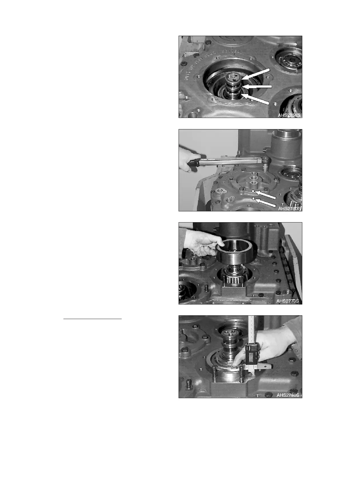
24. Grease and align rectangular rings (3x,
Figure 327) and align them centrically.
25. Install two adjusting screws. Line up the
bearing cover using hex. head screws and
pull it uniformly against shoulder.
NOTE:
Torque limit (M10/8.8) 46 Nm
(34 ft lb).
NOTE:
Pay attention to the radial
installation position, see
markings (Arrows).
26. Adjust bearing preload of Clutch KR/K2 =
0.20 - 0.25 mm (0.0079 - 0.0098 in)
(Figure 329 - Figure 332).
A. Insert outer bearing race until contact
is obtained.
Housing dimension: Determine
Dimension I from outer bearing race
to mounting face.
NOTE:
Dimension I e.g. 15.68 mm
(0.6173 in).
Figure 327
Figure 328
Figure 329
Figure 330