S0607080K
Page 158
Transmission and Torque Converter
(ZF 4WG-310)
F. Install inductive transmitter N-Engine
(14), see Figure 409.
NOTE:
Torque limit 30 Nm (22 ft lb).
NOTE:
Set and install the inductive
transmitter n-Turbine (6) and n-
Central gear train (39)
accordingly.
NOTE:
Pay attention to the different
setting dimensions. Installation
position of the single inductive
transmitters, see also page
160.
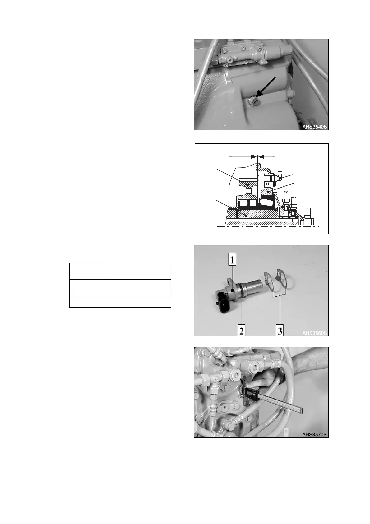
4. Install Speed sensor N-Output/
Speedometer (31) (Figure 410 - Figure
415).
NOTE:
Setting dimension X = 1.0
+ 0.5
mm (0.0394
+ 0.0197
in).
A. Figure 411, shows the speed sensor
(Hall sensor).
B. Determine Dimension I from the
housing face to the spur gear K3.
NOTE:
Dimension I e.g. 39.20 mm
(1.5433 in).
Reference
Number
Description
1 Speed Sensor
2 O-ring
3 Setting Plate(s)
Figure 409
31
1
2
3
X
AHS3550S
Figure 410
Figure 411
Figure 412