TDR9000
™
Circuit Breaker Test System User’s Guide
72A-1898 Rev. A 11/01 4-15
Monday, November 26, 2001 1:09 pm
In many cases the transducer cannot be attached directly to the moving
contact portion of a live tank circuit breaker mechanism. In such cases, it
should be attached to another part of the mechanism whose movement is
related to the one being measured through the Transfer Function. Often,
this mounting location is found near the semaphore, which indicates the
status of the circuit breaker. For a full discussion of the transducer’s
Transfer Function, see ”Transfer Function” on page A-58. Configuration
of transducers is discussed in ”Linear Transducer and Rotary
Attachments” on page 4-16.
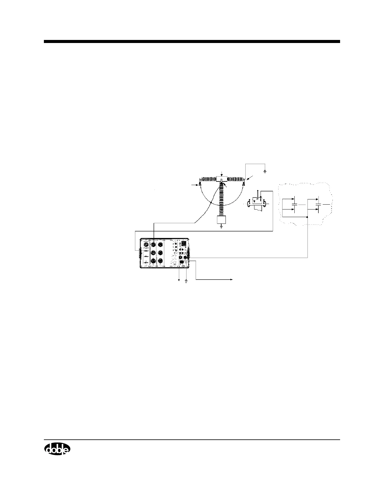
Figure 4.3 shows the cable interconnections for the Live Tank test.
Figure 4.3 Cable Interconnection Diagram – Live Tank
Make sure that
one side of each
phase is
grounded.
Contact Monitor
Cable
Motion Transducer Cable
AC Power
Supply Cable
Safety
Cable Ground
TDR9000
Contact2
Module 1
Phase A
Breaker Control Circuit
in the Control Cabinet
−
DC +DC
Breaker (Trip/Close) Control Cable
Close
Close
Tr ip
Tr ip
52CS
C
52CS
T
Common
Contact 1


 To Next Page