TDR9000
™
Circuit Breaker Test System User’s Guide
72A-1898 Rev. A 11/01 2-3
Monday, November 26, 2001 1:09 pm
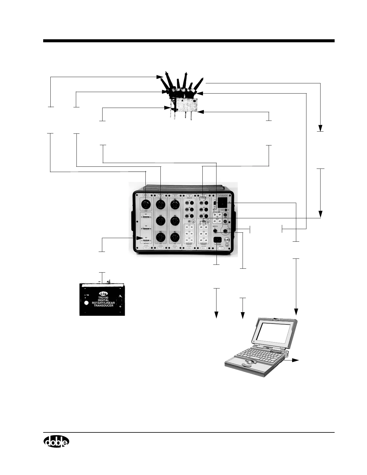
Figure 2.2 TDR9000
™
System Topology
Laptop Runs
TRX Field
• Virtual Front Panel
• Graphical Results
• Tabular Results
• Test Plan
Rotary/Linear Transducer
TDR9000
Motion
Transducer
Cable
To A C
Power
Source
Auxiliary
Contacts
Cables
Analog Voltage/Current
Measurement Cables
(Shunts & Probes)
Mechanical Performance
Contact travel and
velocity
Electrical Performance
A. Auxiliary contacts status
B. Current measurement
C. Voltage measurement
Electrical Performance(OCB or EHV)
A. Contact status/Timing
B. Insertion resistors measurement
Dead
Monitor
Cable
Safety
Cable
(Operator
Control)
RS-232
Communications
A. Remote control
of Circuit Breaker under test
B. Control current
measurements
Trigger In
To TRX Serve
in the office
Trigger In
using
Breaker
(Trip/Close)
Control
Cable
Cables
/Trigger Out
C. Capacitance measurement
Tank
Contact
Live
Cable
Tank
Contact
Monitor
(Event)