System
2-8 72A-1898 Rev. A 11/01
Monday, November 26, 2001 1:09 pm
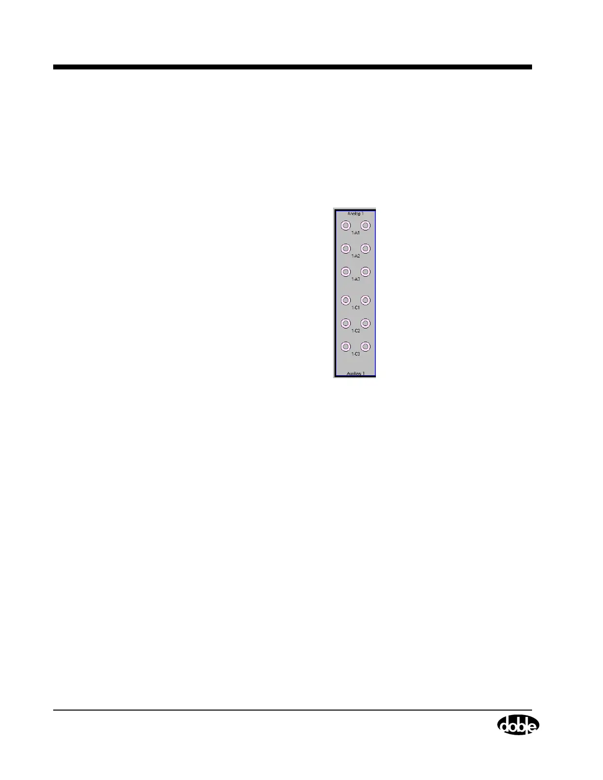
Analog Channels The analog section of the Event module has three general purpose analog
inputs configurable to read voltages directly or to read currents from
Doble current shunts and probes (401-0055).
Auxiliary Contact The Auxiliary Contact section of the Event module monitors the state of
up to three sets of auxiliary contacts.
Figure 2.6 shows the available configurations for the EVENT module.
Figure 2.6 Event Module Configurations
System
The System module is minimally comprised of:
• Power switch/Circuit Breaker
• PC RS-232 communications connector
• Safety switch input connector
• AC power supply plug
• System ground connector
Two options are available which add to the functionality of the
TDR9000:
• Automatic Trip/Close Control – with or without internal current
measurement on Trip/Close control leads
• Triggers