TDR9000
™
Circuit Breaker Test System User’s Guide
72A-1898 Rev. A 11/01 4-45
Monday, November 26, 2001 1:09 pm
Configuring the
OCB/Motion
Module
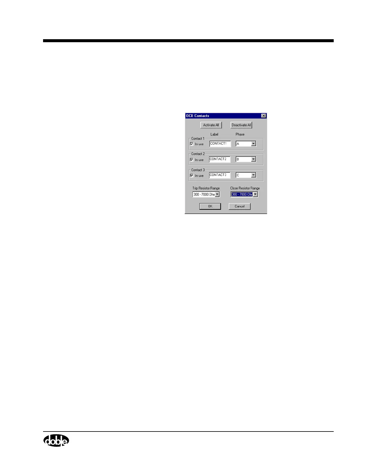
Figure 4.21 shows the OCB Contacts window. The OCB portion of this
module uses one window to configure all three contacts. To access this
window:
• Click the OCB connector or OCB label, for example,
CONTACT1, as shown in Figure 4.20.
Figure 4.21 OCB Contacts
The following items are configurable:
In use A checkbox that activates or deactivates the
associated channel.
Label A user-entered field for entering the Contact Name
associated with the channel.
Phase A scrollable picklist for selecting the phase
associated with the channel.
Trip Resistor Range
A scrollable picklist for selecting the Trip Resistor
configuration. If the resistor is not present, None
should be selected.
The choices are:
•None (default)
• 10 - 400 Ohms
• 300 - 7000 Ohms