Configuration Levels
3-8 72A-1898 Rev. A 11/01
Monday, November 26, 2001 1:09 pm
For the EHV module, this window sets the following parameters that
affect all the active channels:
• Activate/Deactivate All
• Trip Resistor Range
• Close Resistor Range
• Capacitor Range
On the same window, the following parameters affect only individual
connectors that are configured:
•In Use
• Capacitance
• Label (Not editable in EHV)
The OCB/Motion Virtual module (leftmost panel, location one, in
Figure 3.2 on page 3-4), contains an OCB connector and a Motion
connector. This module is effectively split in two, with the overall Motion
parameters window accessed by clicking Motion on the bottom of the
virtual module, and the overall OCB parameters accessed by clicking
OCB on the top of the virtual module. This behavior holds true for the
Event module (panel locations four and five of Figure 3.2 on page 3-4) as
well.
Connector
The connector level accesses only those fields that dictate the behavior of
individual connectors. To open this window for a particular connector,
click its virtual image.
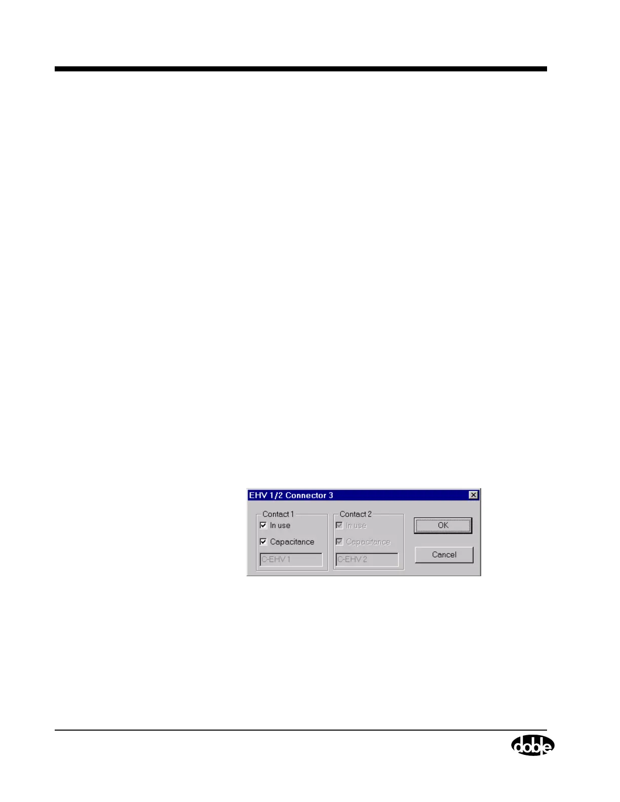
Figure 3.6 shows the connector level window for an EHV connector.
Figure 3.6 Connector Level Configuration