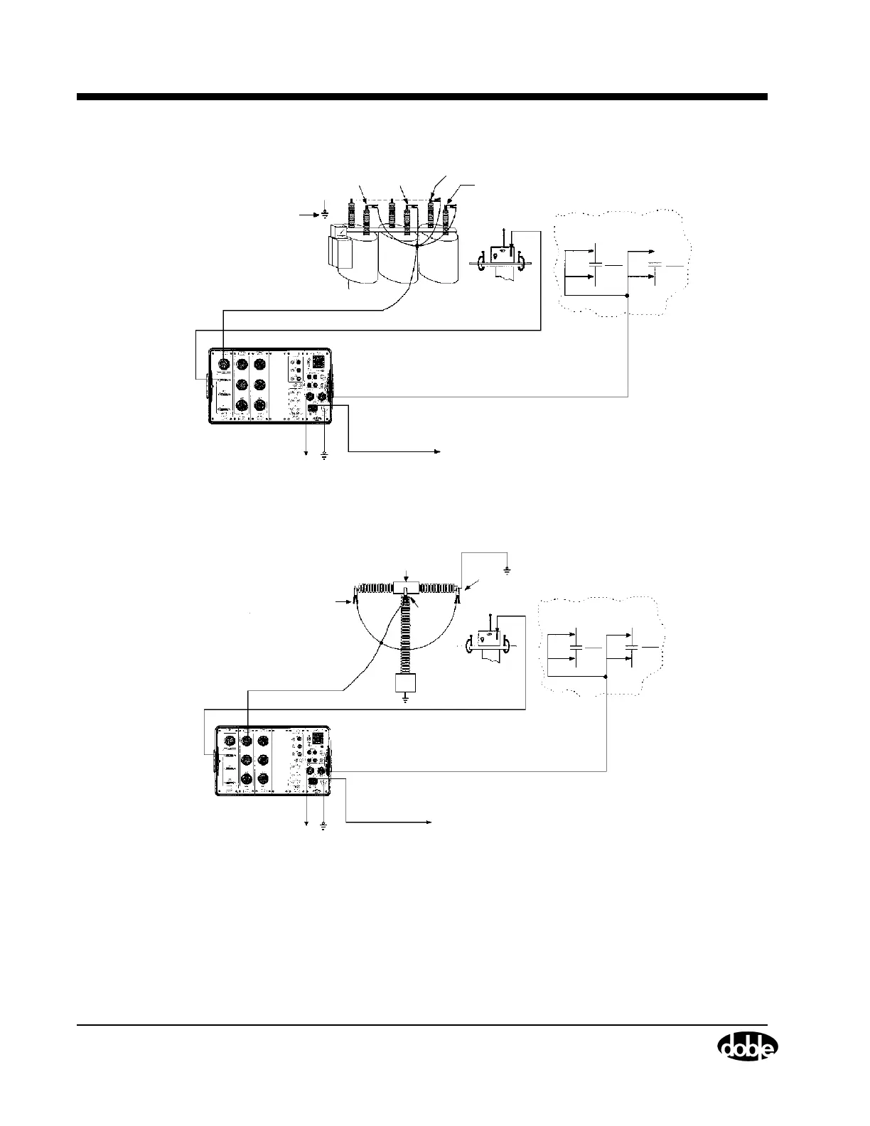
Step 3: Circuit Breaker Connections
1-12 72A-1898 Rev. A 11/01
Monday, November 26, 2001 1:09 pm
Figure 1.6 Step 3: Dead Tank Test Setup
Figure 1.7 Step 3: Live Tank Test Setup
Make sure that
one side of each
phase is
External Ground
Connection
Contact 1
Phase A
Contact 2
Phase B
Common
Contact 3
Phase C
Contact Monitor Cables
grounded.
Motion Transducer Cable
Breaker (Trip/Close) Control Cable
AC Power
Supply Cable
TDR9000
Safety
Cable
Ground
Close
Close Trip
Trip
52CS
C
52CS
T
Breaker Control Circuit
in the Control Cabinet
Make sure that
one side of each
phase is
grounded.
Contact Monitor
Cable
Motion Transducer Cable
AC Power
Supply Cable
Safety
Cable Ground
TDR9000
Contacts
Module 1
Phase A
Breaker Control Circuit
in the Control Cabinet
−
DC +DC
Breaker (Trip/Close) Control Cable
Close
Close
Trip
Trip
52CS
C
52CS
T
Common
Contact 1