Step 1: Circuit Breaker Preparation
1-4 72A-1898 Rev. A 11/01
Monday, November 26, 2001 1:09 pm
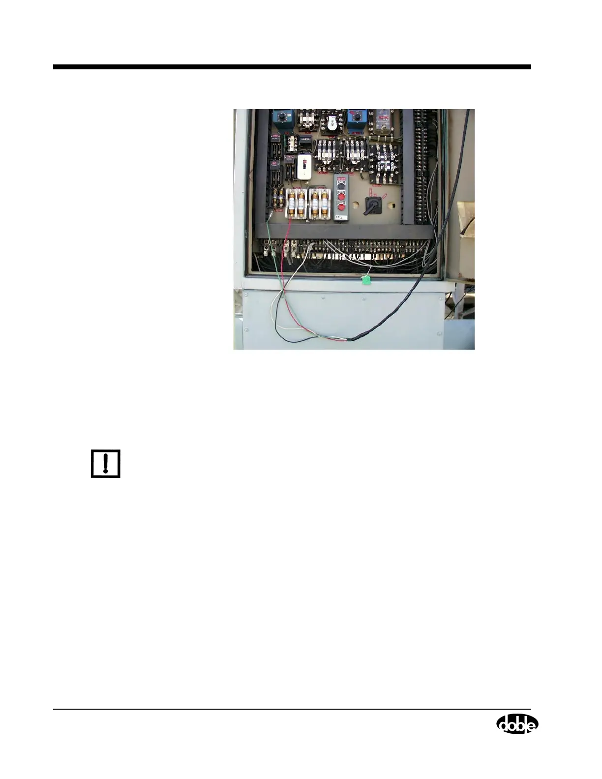
Figure 1.1 Step 1: Circuit Breaker Control Cabinet Preparation
Circuit Breaker
Connections:
First Trip/Close Test
The connections to the breaker are outlined in the steps below:
N
OTE
Once this is complete skip to ”Step 4: Laptop and TDR9000™ Test Plan
Configuration” on page 1-15.
1. Connect the TDR9000 ground connection to circuit breaker ground.
2. Connect a Doble current probe to a CT secondary for each phase
being measured, to record the Main Contact currents.
3. Connect Doble current probes to selected relay coil circuits and then
to TDR9000 event module.
4. Connect a set of Analog cables across the DC supply switch to
monitor the DC bus voltage. Set up the channel for voltage sense and
range.
5. Connect Auxiliary Contact cables across the selected contact and
connect to an Aux contact.