TDR9000
™
Circuit Breaker Test System User’s Guide
72A-1898 Rev. A 11/01 B-25
Monday, November 26, 2001 1:09 pm
If this LED is not lit when the power is applied, then one of the two
power supply fuses is blown, the power supply is bad, the internal
temperature of the Instrument is too high, or the monitoring circuit is bad.
To access the power supply module and examine the fuses:
1. Turn the TDR9000 power off and unplug.
2. Unscrew the two flat head screws that hold the two top rubber feet,
as shown in Figure B.15 on page B-20.
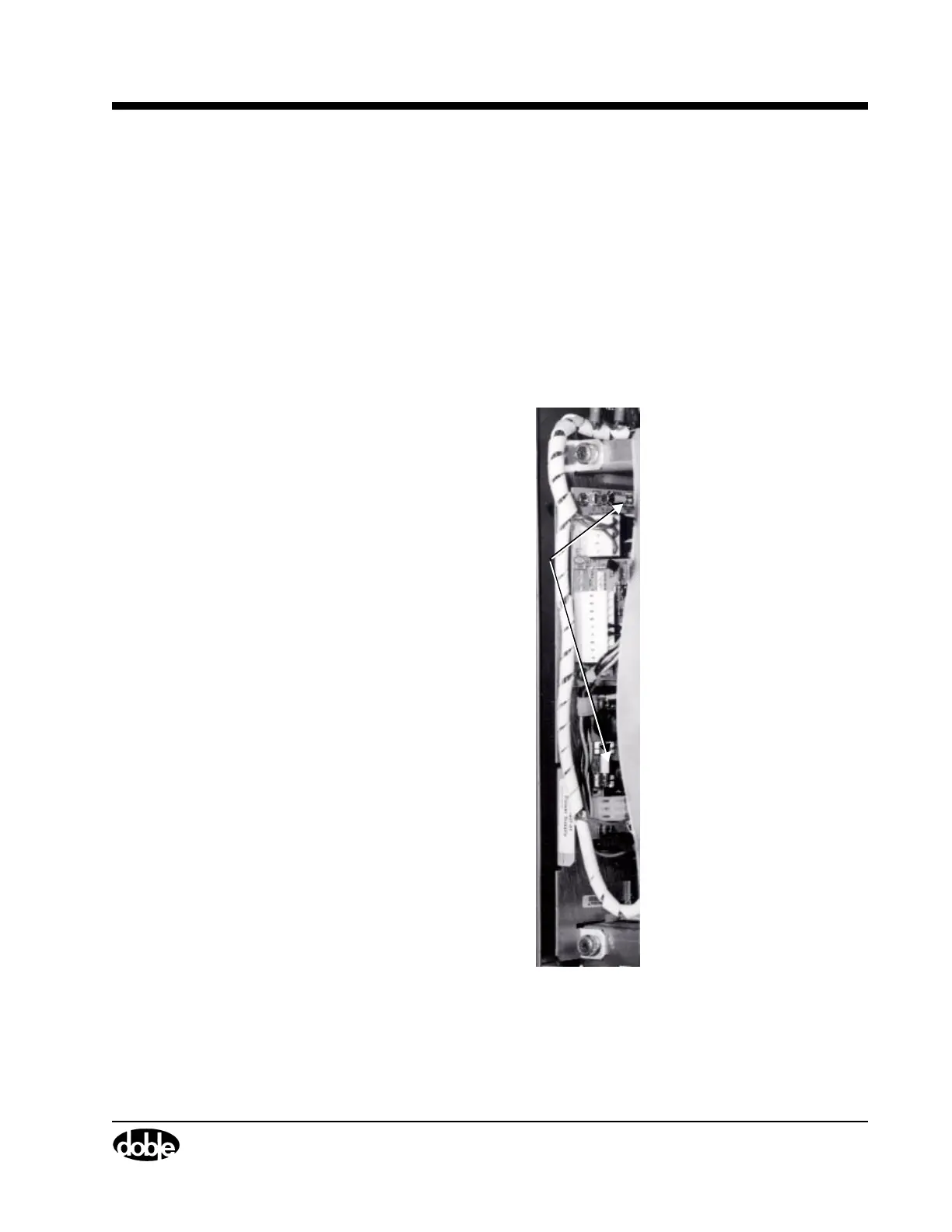
3. Measure the resistance across the fuse using a multimeter. The fuses
are shown in Figure B.17.
Figure B.17 Power Supply Assembly Fuses
Fuses
 Loading...
