TDR9000
™
Circuit Breaker Test System User’s Guide
72A-1898 Rev. A 11/01 2-17
Monday, November 26, 2001 1:09 pm
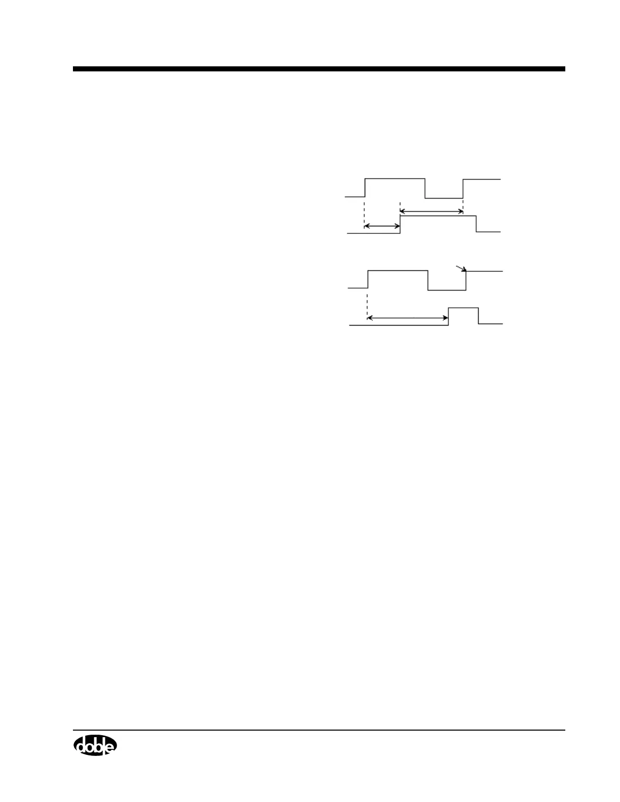
O-C-O
Figure 2.12 gives a simplified representation of the test waveform
generated for the O-C-O test.
Figure 2.12 O-C-O Command Pulse
Command
Parameters
Trip Command This time setting determines the duration of the first
Trip Pulse sent to operate the trip circuit of the
circuit breaker.
Close Command, Delay 1 and Delay 2
These parameters determine when the Close Pulse
is initiated:
Standing
Initiates .5 cycles (8.3 ms at 60 Hz) after the Trip
Pulse. The second Trip Pulse occurs – measured
from the start of the Close Pulse – after the time
specified in Delay 2.
Delay
Initiates a Close after the time entered in Delay 1
that appears when Delay is selected. Delay 2 also
appears, which determines when the second Trip
Pulse is sent. Both delays are measured from the
start of the Close Pulse.
Contact 1 Make
Standing and Delay
Trip C ommand
Close Command
Trip C ommand
Close Command
Delay 1
Delay 2
Delay
Contact
Make