TDR9000
™
Circuit Breaker Test System User’s Guide
72A-1898 Rev. A 11/01 B-27
Monday, November 26, 2001 1:09 pm
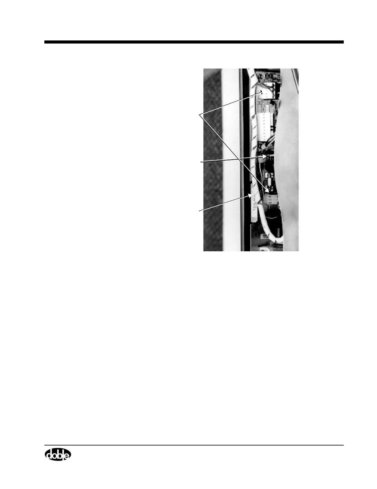
Figure B.18 Power Supply Circuit Board Connectors
5. Pull up gently on the metal tab (Figure B.18) to remove the assembly.
6. Insert the replacement assembly into the guides and gently push it
into position.
7. Replace the cables disconnected in step 4.
8. Plug the unit in and power up the TDR9000.
9. Check the LED on the System module Physical Front Panel.
If LED is not green, refer to the Troubleshooting Flow Charts starting
on page B-11.
10. Replace the top cover and reinstall the two rubber feet.
Metal Tab
Connector
Green
Ground Wire