TDR9000
™
Physical and Virtual Front Panel Numbering
3-14 72A-1898 Rev. A 11/01
Monday, November 26, 2001 1:09 pm
EHV Module
Numbering
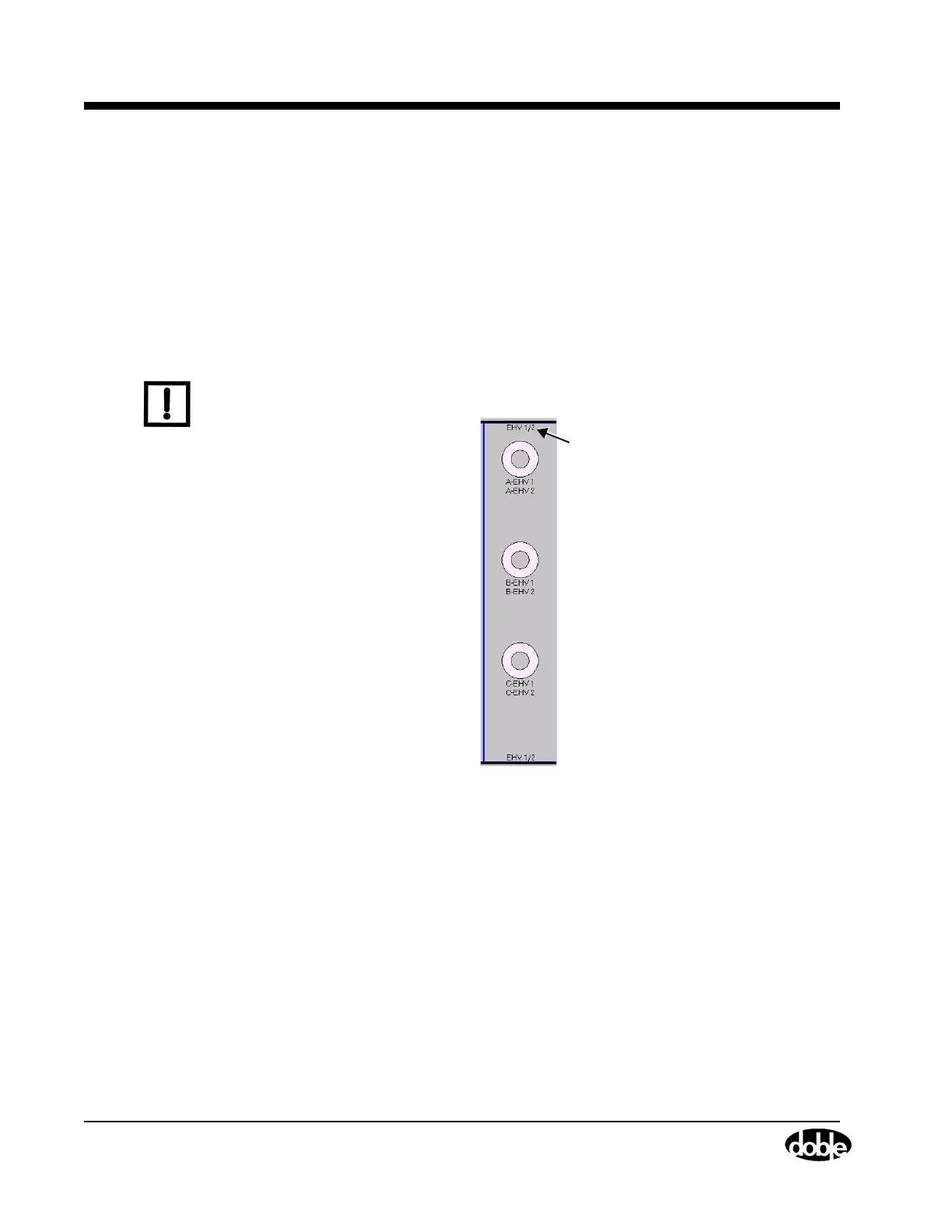
The numbering that appears on the EHV Virtual Front Panel module
represents the circuit breaker contacts to be monitored by that module.
Figure 3.11 shows an example EHV module. In this example, 1/2
designates that this EHV module should be connected to contacts 1
and 2 of the EHV circuit breaker.
The first available location is Location 2. EHV modules in Location 2 are
referred to as EHV1, EHV modules in Location 3 are referred to as EHV2,
and so on.
Note
Ensure that the physical connections completed on the Physical Front
Panel reflect this numbering order.
Figure 3.11 Virtual Front Panel EHV Module Numbering
Event Module
Numbering
The Event module itself is numbered according to the location it
populates in the TDR9000. This label appears at the top and the bottom
of the module prefaced by Analog and Auxiliary, respectively.
The Analog and Auxiliary connectors, which occur in groups of three per
module, are numbered from top to bottom.
Module
Numbering