Circuit Switchers and High-Current Generator Breakers with Isolating Contacts
A-22 72A-1898 Rev. A 11/01
Monday, November 26, 2001 1:09 pm
Understanding Contact Measurement
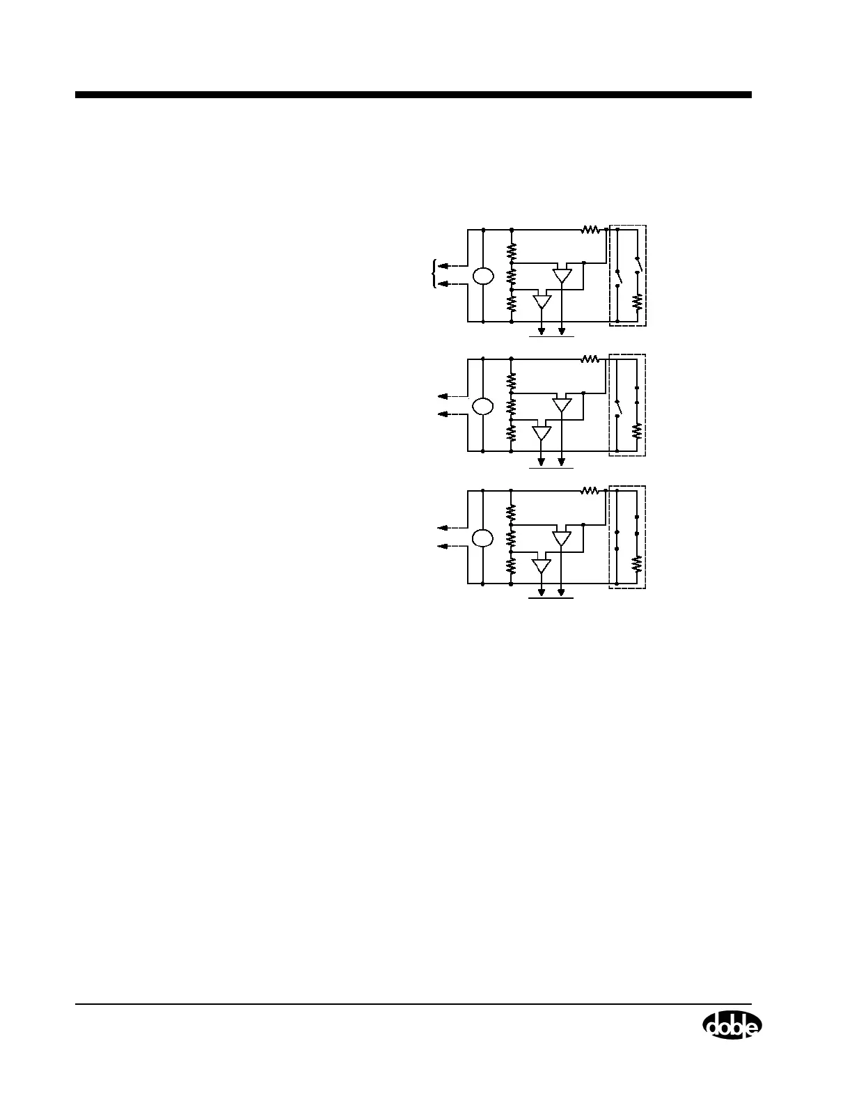
Figure A.22 displays a typical circuit used to monitor contact status.
Figure A.22 Contact Monitoring
Both Main contact and
resistor switch open.
To another
measuring
module.
Main contact open,
Resistor Switch closed.
Both Main contact and
Resistor switch closed.
75
Ω
75
Ω
75
Ω
75
Ω
75
Ω
75
Ω
20 V
±
S
S
S
2 k
16 V
6 k
4 V
2 k
2 k
16 V
6 k
4 V
2 k
2 k
16 V
6 k
4 V
2 k
00
01
11
20 V
10 V
0 V
A
B
A
B
A
B
2
1
2
1
2
1
20 V
±
20 V
±