TDR9000
™
Circuit Breaker Test System User’s Guide
72A-1898 Rev. A 11/01 3-9
Monday, November 26, 2001 1:09 pm
Using this window, the following parameters that affect individual
connectors can be configured:
•In Use
• Capacitance
• Label (Not editable in EHV)
Smart Cursor
To assist in configuring Virtual Front Panel modules, the TRXField
program includes a specialized Smart Cursor. When the mouse pointer is
located near a configurable item, the Smart Cursor appears with text
indicating the module associated with the cursor. The cursor has two
different appearances:
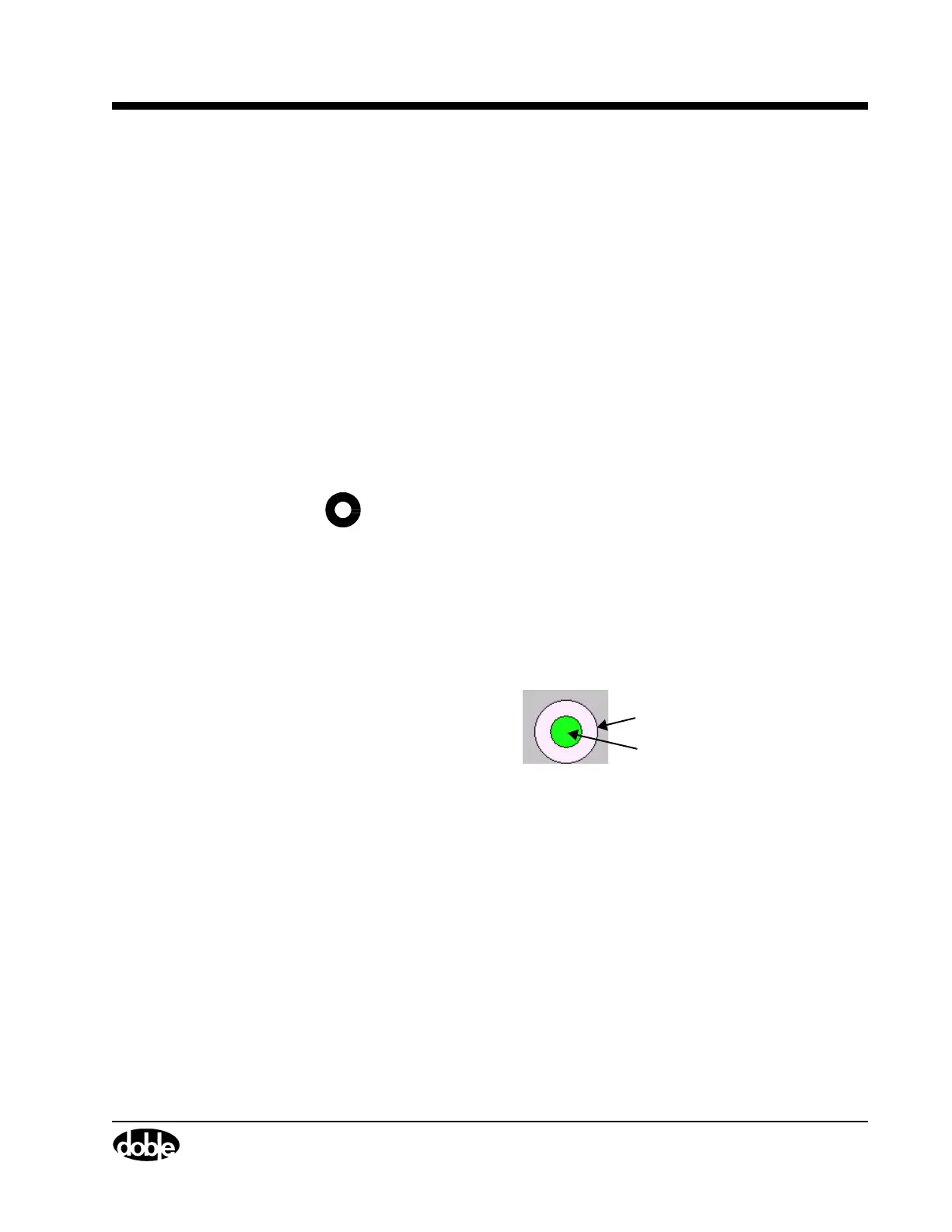
Connector Indications
Figure 3.7 shows an example of an OCB connector with callouts to its
various components (shown as rings). All connectors on the Virtual Front
Panel use the same basic functionality, where color designates status.
Figure 3.7 Sample Connector
A Indicates the channel activation status. Channels
are activated or deactivated using the In Use
checkbox on the various connector configuration
windows or on the Test Plan tab. For this
component:
• White indicates an active channel
• Blue indicates an inactive channel
Clicking the mouse when this cursor appears opens the
Module level configuration window, as explained in
”Module” on page 3-7.
Clicking the mouse when this appears opens the
Connector level configuration window, as explained in
”Connector”.
◆
◆
◆
A
B