TDR9000
™
Circuit Breaker Test System User’s Guide
72A-1898 Rev. A 11/01 4-53
Monday, November 26, 2001 1:09 pm
Auxiliary
Channels
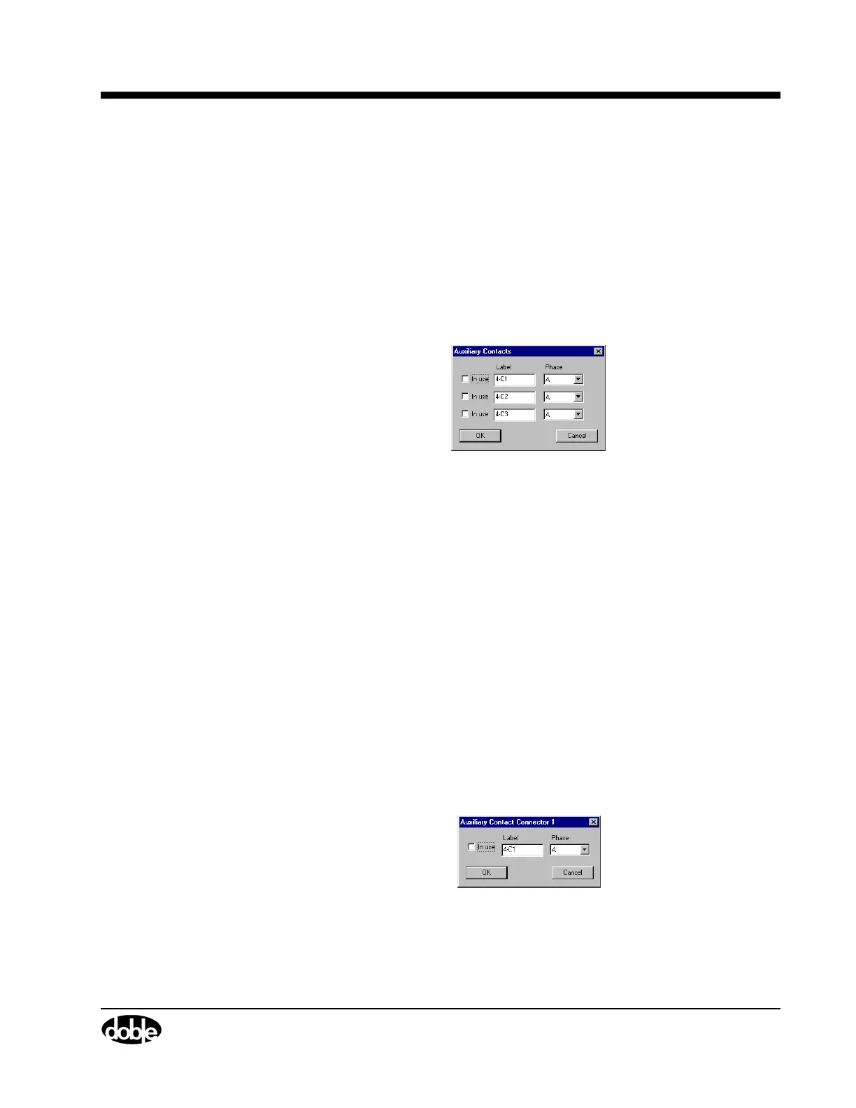
Figure 4.28 and Figure 4.29 show the Auxiliary Contacts and the
Auxiliary Contact Connector windows, respectively.
The Auxiliary Contacts window configures all three channels using one
window.
To access this window:
• Click the Auxiliary label on the bottom of the virtual module, as
shown in Figure 4.20 on page 4-44.
The window shown in Figure 4.28 appears.
Figure 4.28 Auxiliary Channels – Collective
The following items are configurable:
In use A checkbox that activates or deactivates the
associated channel.
Label A field for entering the name associated with that
channel.
Phase A scrollable picklist for selecting the phase
associated with the channel.
An Auxiliary Contact Connector window is available for each available
analog channel.
To access this window:
• Click any Auxiliary connector or channel label, for example,
4-C1, as shown in Figure 4.20 on page 4-44.
The window shown in Figure 4.29 appears.
Figure 4.29 Auxiliary Contact Connector – Individual
The configurable items are identical to those in ”Auxiliary Channels”.