Configuring Test Plans
4-52 72A-1898 Rev. A 11/01
Monday, November 26, 2001 1:09 pm
The following items are configurable:
In use A checkbox that activates or deactivates the
associated channel.
Label A field for entering the name associated with that
channel.
Range A scrollable picklist for selecting the voltage range,
current probe range or current shunt range. The
choices are:
•.2 V
•2 V
• 10 V
• 300 V
• 20 A Current Probe
• 200 A Current Probe
• Current Shunt 200 mV
• Current Shunt 2 V
• Current Shunt 10 V
Phase A scrollable picklist for selecting the phase
associated with the channel.
An Analog Channel Connector window is available for each available
analog channel.
To access this window:
• Click any Analog connector or channel label, for example, 4-A1,
as shown in Figure 4.20 on page 4-44.
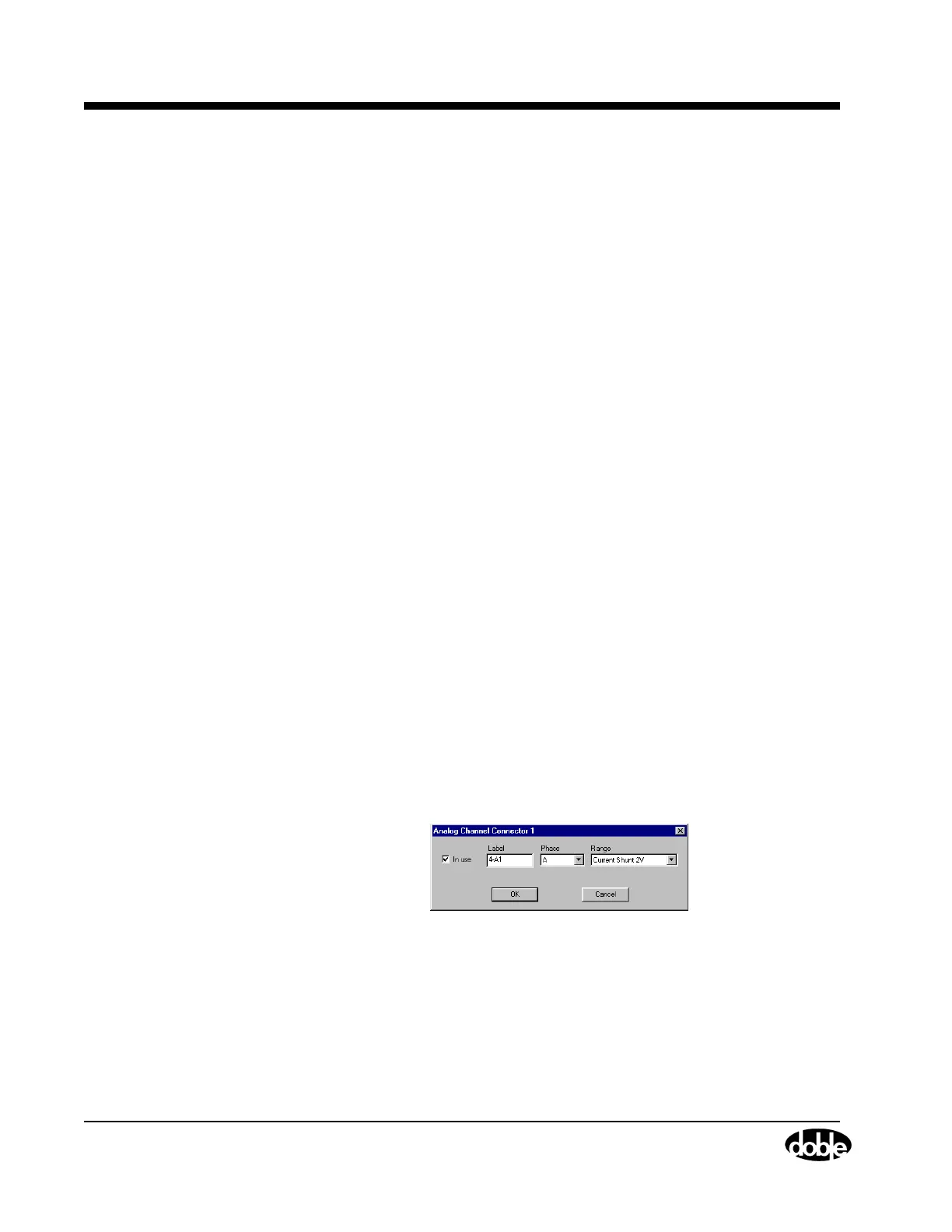
The window shown in Figure 4.27 appears.
Figure 4.27 Analog Channel Connector – Individual
The configurable items are identical to those explained above.