Test Plan Items
A-52 72A-1898 Rev. A 11/01
Monday, November 26, 2001 1:09 pm
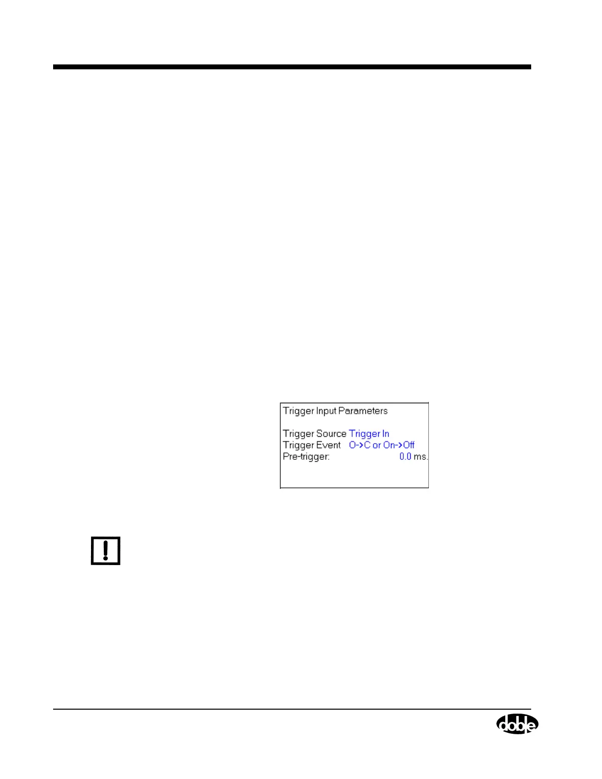
Trigger In A System Trigger In (Figure A.64) functions
somewhat differently than an AUX Contact Trigger
In. An input that comes in through the External
Trigger connection of the System module and is
conditioned by a delay time, starts the TDR9000
test.
Although the System module Trigger In channel is
a tri-state channel like the Aux Contact channel, it
is not a measurement channel. For each of the two
settings, it detects the state change, but only the
fact that a trigger event has occurred is sent to the
firmware.
Trigger In detects two different sets of Either/Or
conditions.
• Open to Closed or On to Off
Use this setting to detect a transition either from
Open to Close or Volts On to Volts Off.
• Closed to Open or Off to On
Use this setting to detect a transition either from
Close to Open or Volts Off to Volts On.
Figure A.64 TDR9000
™
System Trigger In Parameters
N
OTE
Only the Trigger In channel on the System module is rated for 600 V
peak operation.
The System Trigger In channel cannot be in the
active state when the test is started. The active state
is the second state of the trigger event transition. In
an Open to Close transition, closed is the active
state. Therefore, if Open to Close or On to Off is
selected, and Continue is clicked while the Trigger
In channel is connected across a closed switch, the
test is aborted because the trigger input is already
in the active state.