TDR9000
™
Circuit Breaker Test System User’s Guide
72A-1898 Rev. A 11/01 3-15
Monday, November 26, 2001 1:09 pm
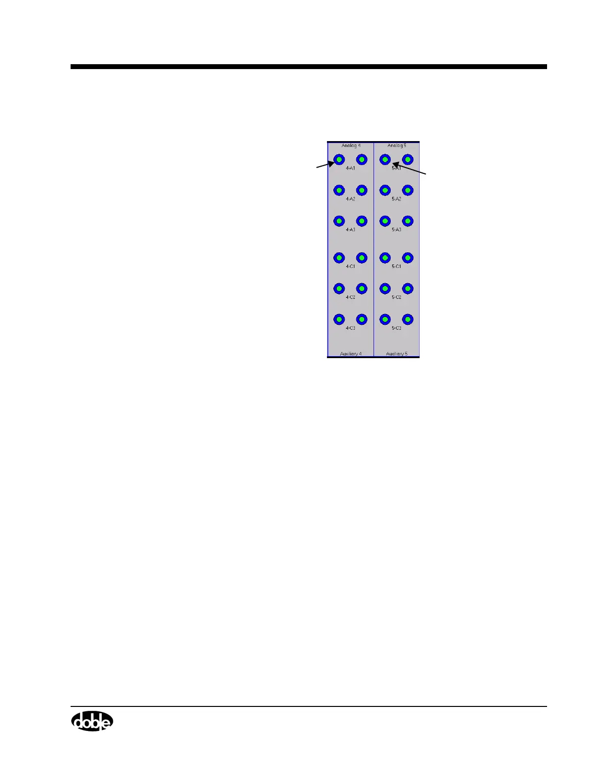
Figure 3.12 shows an example with two Event modules side-by-side on
the same Virtual Front Panel and explains module numbering syntax.
Figure 3.12 Virtual Front Panel Event Module Numbering
A discussion of each module type follows. Each discussion contains:
• A description of module functionality.
• A graphic that maps the relationship between the Physical Front
Panel and the Virtual Front Panel, using the related TRXField Test
Plan parameters as a bridge.
In graphics, bracketed Test Plan items between the Physical Front
Panel connector and the Virtual Front Panel are the only
configurable using the Test Plan tab. These items must be active
in a Test Plan imported from the TRX software If configuring a
new plan, they are configurable only on the Test Plan tab.
Analog Connection
Analog Connection
numbering for
Location 4
(
4-A1)
numbering for
Location 5
(
5-A1)