TDR9000
™
Circuit Breaker Test System User’s Guide
72A-1898 Rev. A 11/01 A-43
Monday, November 26, 2001 1:09 pm
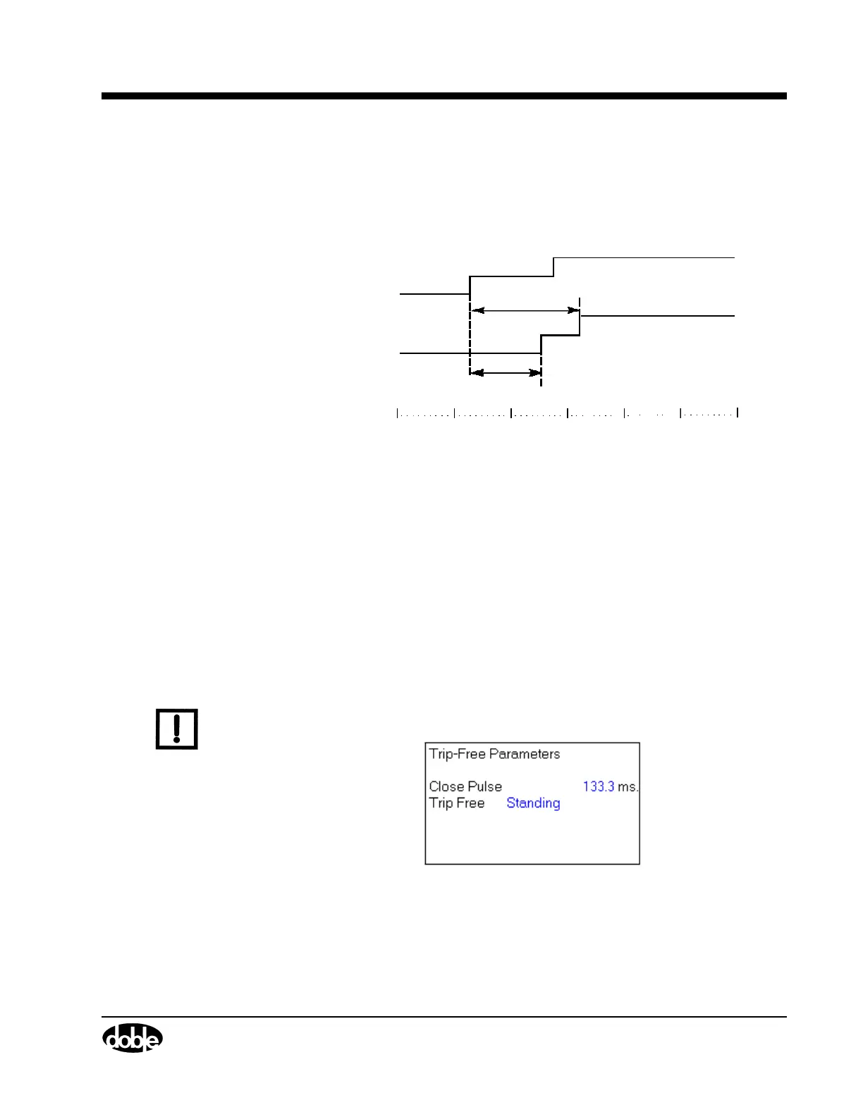
The selection made calculates the timing of the Main Contact (t
2
) and
resistor switch (t
1
) (Figure A.45), after the first transition of the auxiliary
contact, measured by channel 5-C1 in the TDR9000, if the T0 option is
selected in ”Resistor Switch Timing – Close” on page A-77.
Figure A.45 Transition of Contact
Trip Free
Parameters (C-O)
The close pulse and the delay length are adjustable in 1/10 ms
increments.
1/2 Cycle
The following options are available for the trip initiation command:
• Standing
• Delay
• Contact 1 Make
Standing The trip pulse is applied 8.33 ms (1/2 cycle) for 60 Hz (10 ms for 50 Hz)
after the close pulse and continues for the duration of the test
(Figure A.46).
N
OTE
If the 1/2 cycle delay must be eliminated, the Trip-Free test with delay
option set to 0.0 ms should be used.
Figure A.46 Trip Free Standing
The default Close Pulse value is:
• 60 Hz - 133.3 ms
• 50 Hz - 160 ms
Channel 5-C1
Open Wet
Open Dry
Closed
t
2
t
1
0 102030405060
Time (ms)