TDR9000
™
Circuit Breaker Test System User’s Guide
72A-1898 Rev. A 11/01 4-51
Monday, November 26, 2001 1:09 pm
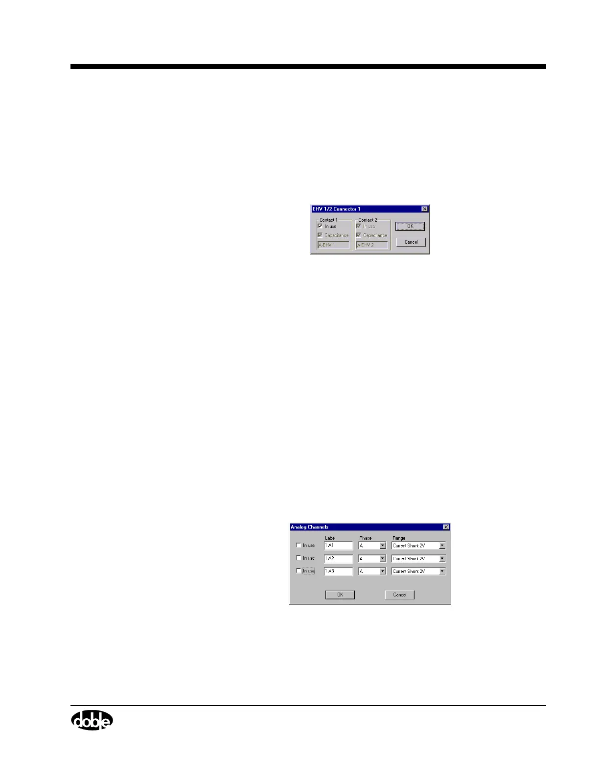
Figure 4.25 shows the EHV Connector window. To access this window:
• Click any EHV connector or channel label (for example,
A-EHV 1), as shown in Figure 4.20 on page 4-44.
There is an EHV Connector window for each configured EHV
channel. This window configures only items specific to an individual
EHV channel.
Figure 4.25 EHV Connector – Individual
The configurable items are the same as explained for individual EHV
channels, above.
Configuring the
Event Module
The Event module is comprised of six sets of virtual connectors:
• Three analog measurement connectors that are independently
configured for either currents or voltages
• Three auxiliary contact connectors
Analog Channels Figure 4.26 and Figure 4.27 on page 4-52 show the Analog Channels
and the Analog Channel Connector windows, respectively.
The Analog Channels window configures all three channels using one
window.
To access this window:
• Click the Analog label on the top of the virtual module, as shown
in Figure 4.20 on page 4-44.
The window shown in Figure 4.26 appears.
Figure 4.26 Analog Channels – Collective