TDR9000
™
Circuit Breaker Test System User’s Guide
72A-1898 Rev. A 11/01 3-13
Monday, November 26, 2001 1:09 pm
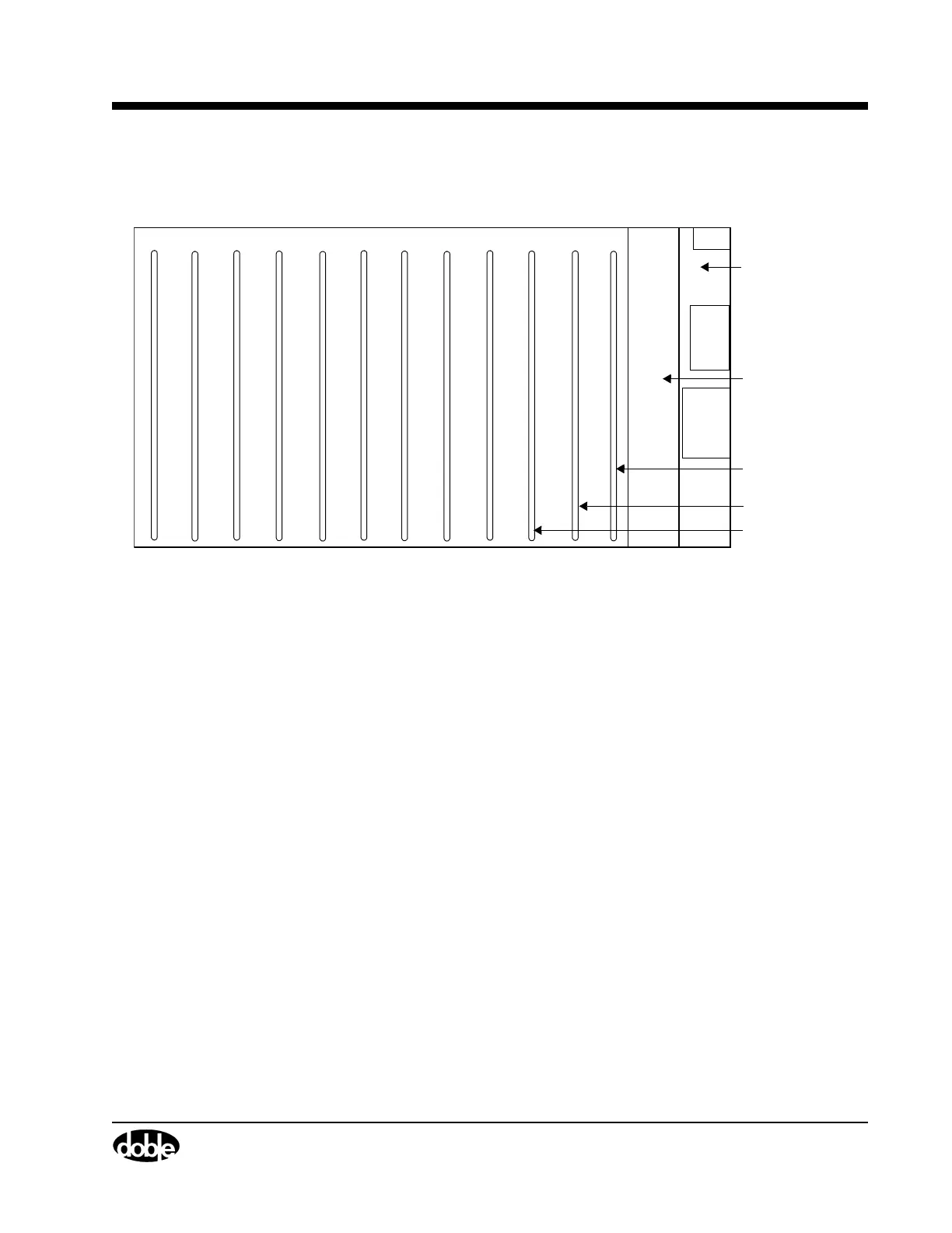
Figure 3.10 shows how numbering develops for the boards that populate
the TDR9000 backplane.
Figure 3.10 TDR9000
™
Backplane Slots - Top View
Since there are twelve backplane Slots and only six Physical Front Panel
Locations for modules, it is apparent that some modules require the use
of two individual boards in two backplane slots to operate. This explains,
for instance, why once a location is configured for an EHV module, an
Event module cannot be placed there. To change module types, when
allowed, a backplane card or cards must also be changed.
When a module requires the use of two Slots, one of these Slots contains
a Master board and one contains a Slave board.
Virtual Front Panel
Numbering
There are two instances where module numbering appears on the Virtual
Front Panel:
• EHV modules
• Event modules
Trip/Close
123456789101112
Slot 1 CPU
Slot 2 EVG
Power Supply
Front of Instrument
Slot 3
Capacitance
Module
Module
(optional)