TDR9000
™
Circuit Breaker Test System User’s Guide
72A-1898 Rev. A 11/01 A-5
Monday, November 26, 2001 1:09 pm
Air-Blast Circuit
Breakers
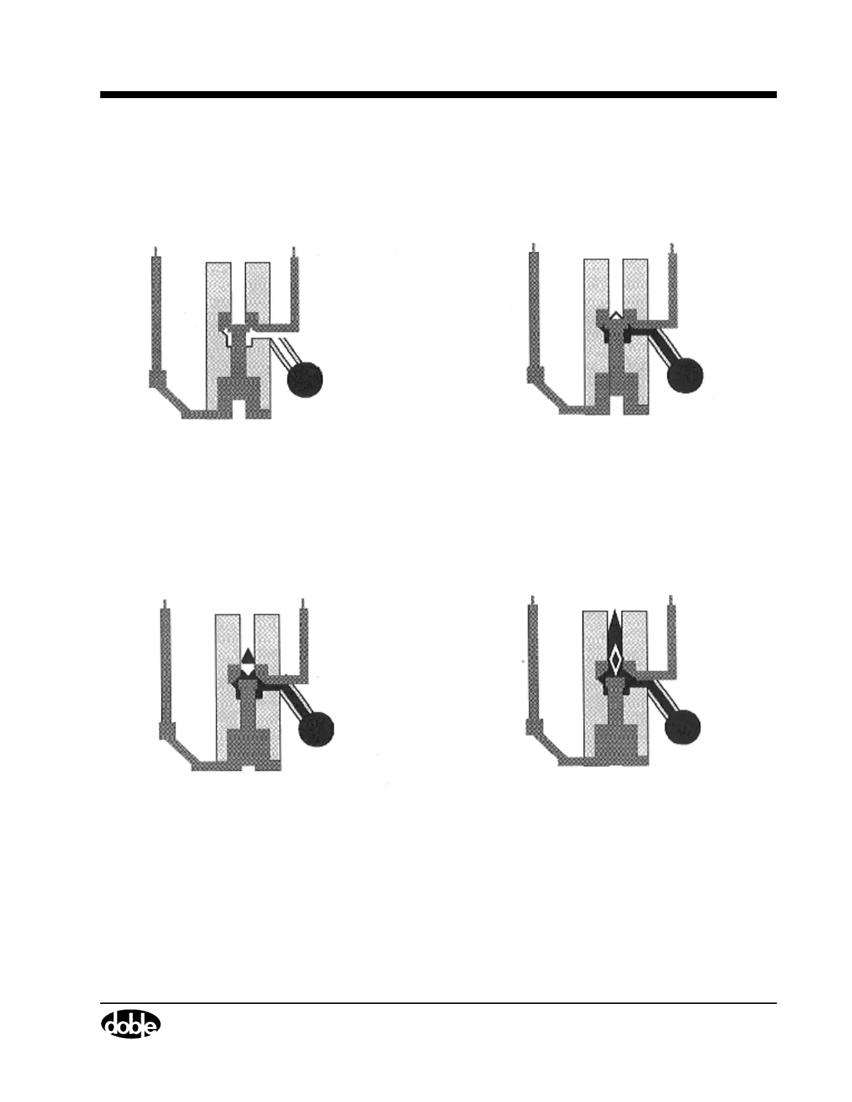
Figure A.4 and Figure A.5 on page A-6 explain the process that occurs
for current interruption in an Air-Blast Circuit Breaker.
This technique is used in the circuit breakers rated up to 46 kV.
Figure A.4 Air-Blast Circuit Breaker Operation
1. Cross section of a circuit breaker showing 2. The trip coil is energized and releases a
3. Air blast continues to force air past the
4. When the air travels and streams alongside
the path of current when the circuit breaker
is in the closed position.
pilot air valve which allows the air to flow from
the breaker tank. This air flows to the contact
chamber and displaces the interrupting contacts.
interrupting contacts as the arc is initiated.
the arc, the arc is enveloped and the arc products
are directed to a cooling chamber.