TDR9000
™
Circuit Breaker Test System User’s Guide
72A-1898 Rev. A 11/01 I-27
Monday, November 26, 2001 1:09 pm
AN7: Monitoring Closing Coil Current with the
TDR9000
™
Current Shunt in the Close Circuit
The TDR9000 system uses one set of control leads to control the
operation of the circuit breaker and to monitor the Trip or Close current.
N
OTE
The TDR9000 close current measurement can handle a maximum of
20 A.
Previous test sets used a relay to initiate the Trip or Close operation. Since
the pickup time of the initial relay varies from test to test, a method to
mark the time of test initiation was necessary. A second set of leads
(sense channel) provided this function and enabled timing from that
reference point on the trace. Since the TDR9000 uses its solid-state
control circuitry to initiate operational tests, this sense circuit is not
necessary. The Trip and Close circuits of the TDR9000 incorporate
optional shunts that enable the instrument to monitor and measure Trip
and Close currents.
Since most Close tests are initiated with the Close leads bridging a
closing contact on a control switch or a push button, the current
monitored is the current that is present in the X relay circuit rather than
the Closing Coil circuit.
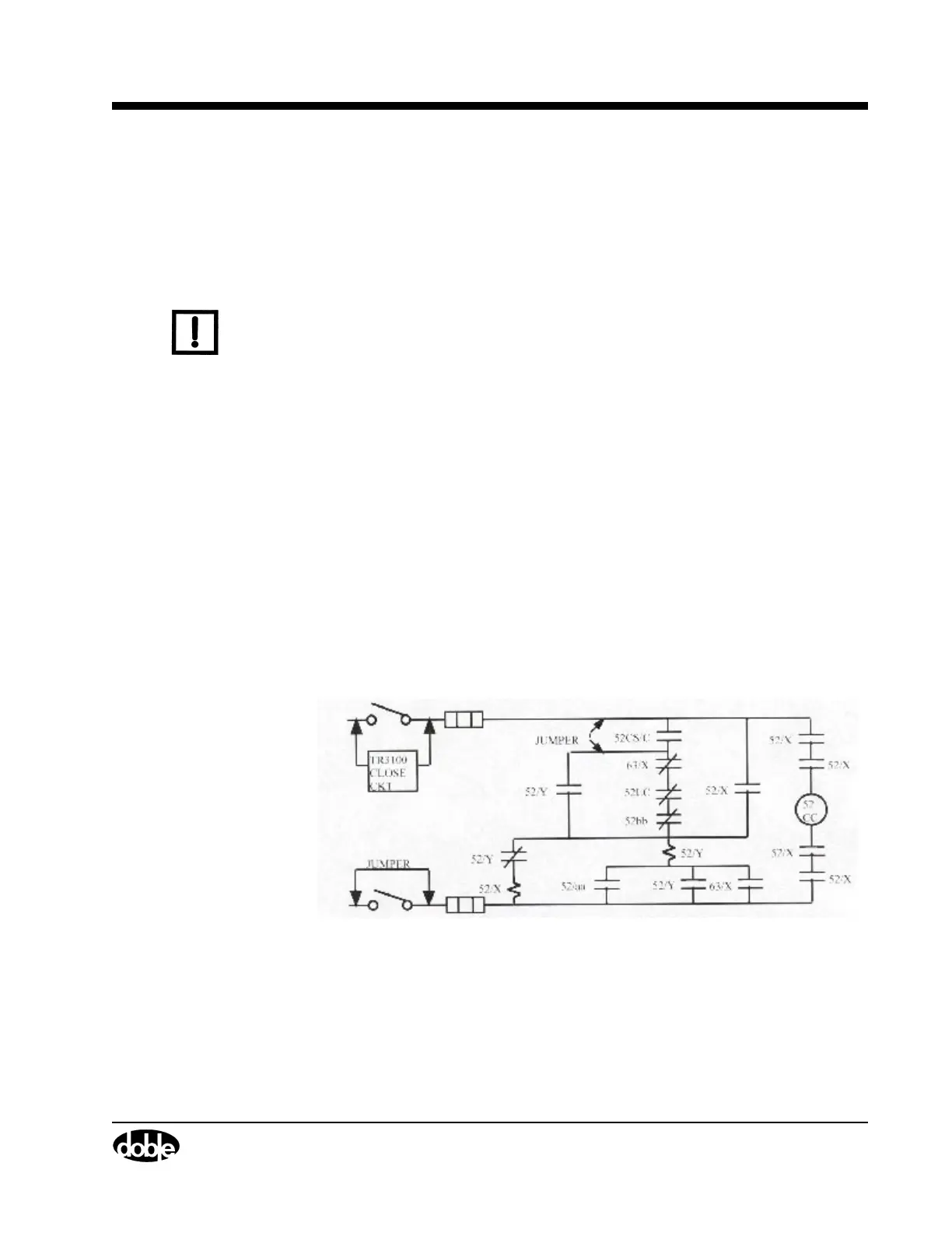
The current in the Close coil circuit can be monitored and measured if a
few temporary clip-to-clip jumpers are added (Figure I.23).
Figure I.23 Jumper Placement

 Loading...