TDR9000
™
Circuit Breaker Test System User’s Guide
72A-1898 Rev. A 11/01 4-17
Monday, November 26, 2001 1:09 pm
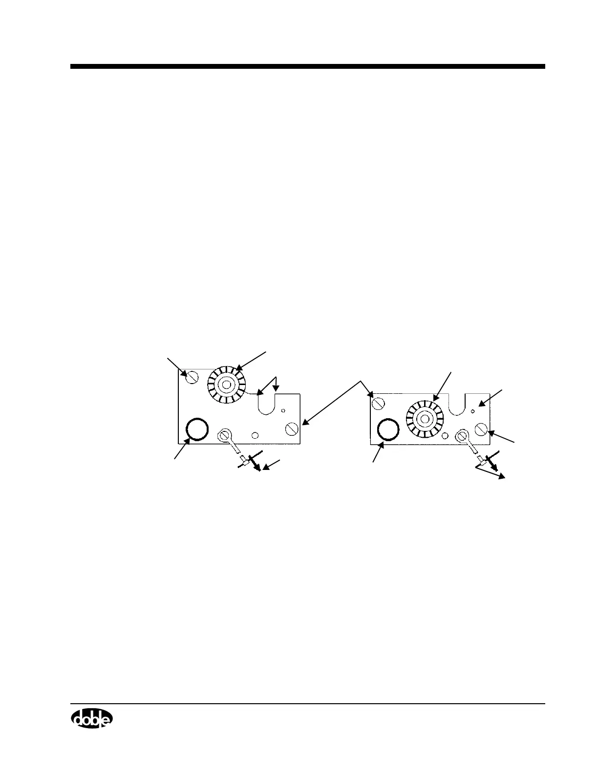
The Chuck Holder Plate is shipped in two different configurations, as
shown in Figure 4.5. This plate provides five different functions:
• When mounted in the ROTARY position
• It depresses a micro-switch that indicates to the TDR9000 that
a rotary measurement is being performed.
• It covers the gate area, which serves as a reminder that it must
be moved to the LINEAR position prior to inserting the travel
rod to perform a linear measurement.
• It includes a metal sheath that covers the Rotary Shaft to ensure
that the threads do not come in contact with any foreign objects
that could cause thread damage during storage or operation.
• It has a cutout that is used as a wrench to hold the Rotary Shaft,
while the Rotary Chuck is loosened or tightened.
• It provides a storage location for the Rotary Chuck when a linear
measurement is made.
Figure 4.5 Chuck Holder Plate Configuration
Version 2Version 1
Chuck Key
Sheath
Rotary Chuck in
Captive
Chuck Key
Rotary Chuck in
Captive
Sheath
Wrench
Captive
Storage Location
Wrench
Screws
Storage Location
Screw
Screw