Step 2: TDR9000
™
Connections
1-8 72A-1898 Rev. A 11/01
Monday, November 26, 2001 1:09 pm
Analog and
Auxiliary Setup
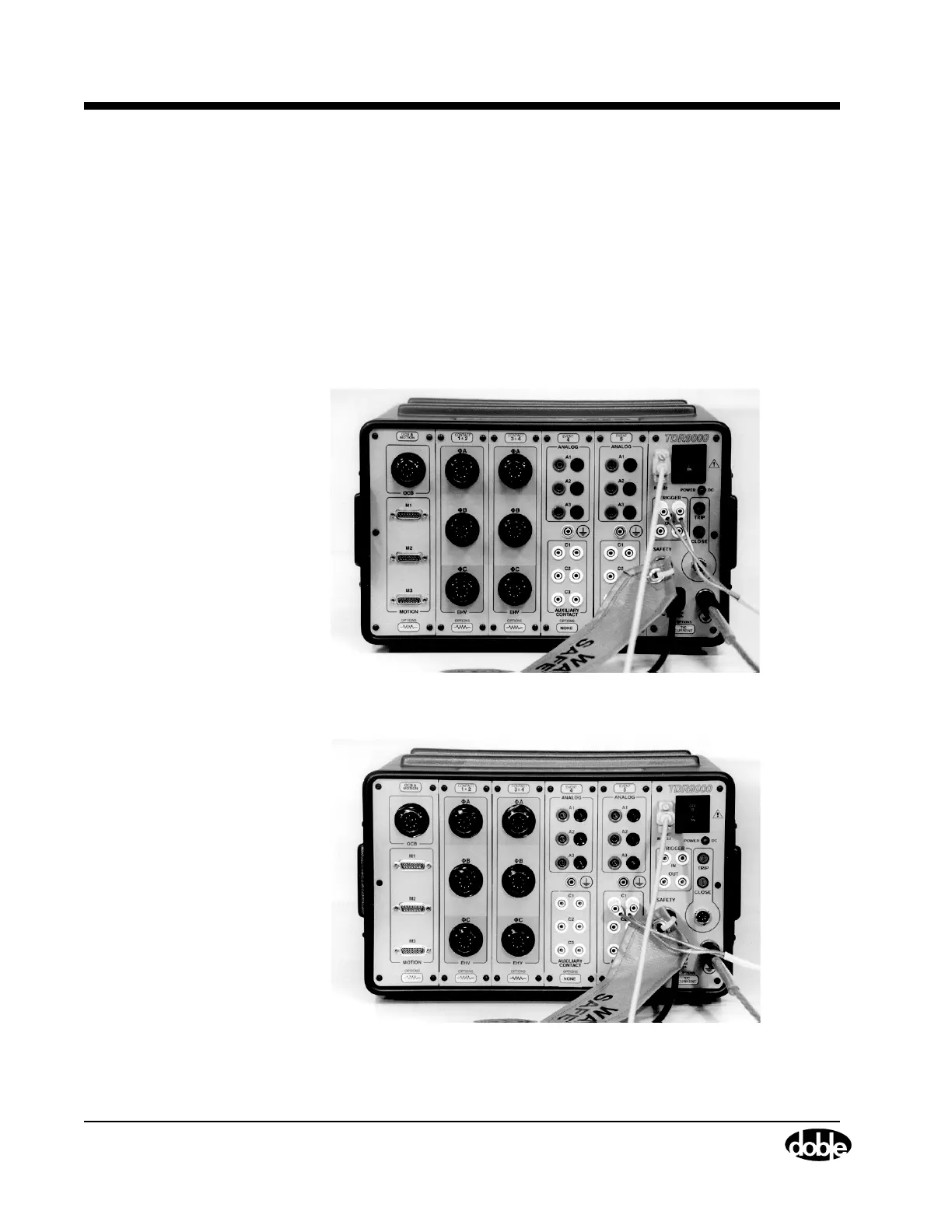
The discussions that follow relate to setup issues for the Event and System
modules (Figure 1.4 and Figure 1.5).
• Refer to ”Monitoring Auxiliary Channels” on page 4-32 to
connect an Auxiliary Contact.
• Refer to ”Monitoring Analog Channels: Current and Voltage”
on page 4-33 to connect a voltage input.
• Refer to ”Current Probes” on page 4-34 to connect and zero a
current probe on the Virtual Front Panel.
• Refer to ”Current Shunt” on page 4-37 to connect a current shunt.
Figure 1.4 Step 2: Physical Front Panel for Trigger In Test
Figure 1.5 Step 2: Physical Front Panel for Auxiliary Input Trigger Test