TDR9000
™
Circuit Breaker Test System User’s Guide
72A-1898 Rev. A 11/01 1-9
Monday, November 26, 2001 1:09 pm
TDR9000
™
Connections:
First Trip/Close
Tes t
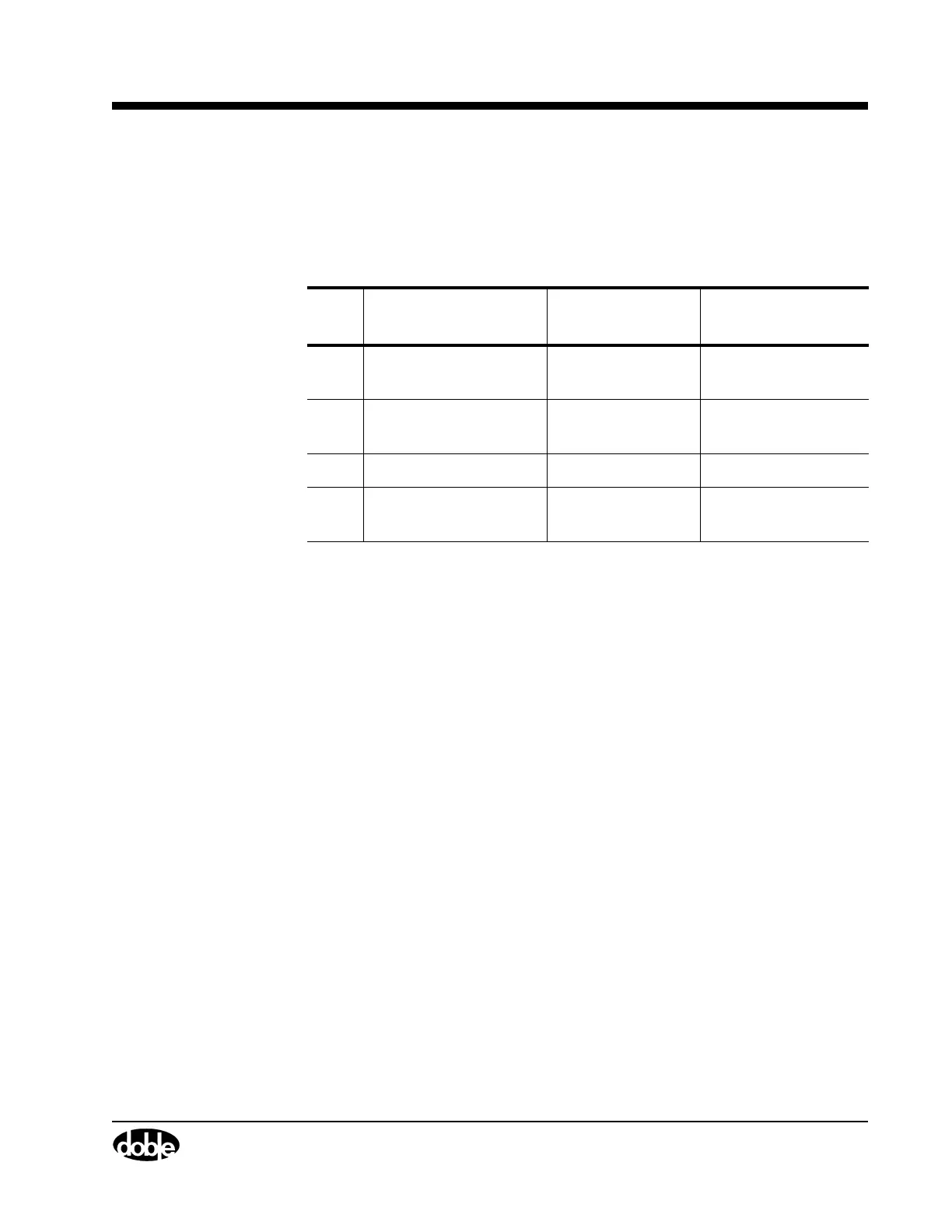
Table 1.3 and Table 1.4 list the connections to the TDR9000 required for
both a minimum set of channels and the recommended set of channels,
respectively. Since this is an external trigger test, no control cable is used.
*Connect to an Event module if using the Aux Contact trigger source, and
to the Trigger In connectors on the System module if using the Trigger In
source. Table 1.3 applies to a TDR9000 with one Event module.
Table 1.3 TDR9000
™
Using a Minimum Set of Channels
Item Signal Type TDR9000 Module
Connection
1 Main Contact
(from CT secondary)
Analog Event
2 Trip relay coil
current
Analog Event
3 DC Supply voltage Analog Event
4 52CS/T contact state
(for Trigger In source)
Auxiliary Contact Event or Trigger In*