Step 2: TDR9000
™
Connections
1-10 72A-1898 Rev. A 11/01
Monday, November 26, 2001 1:09 pm
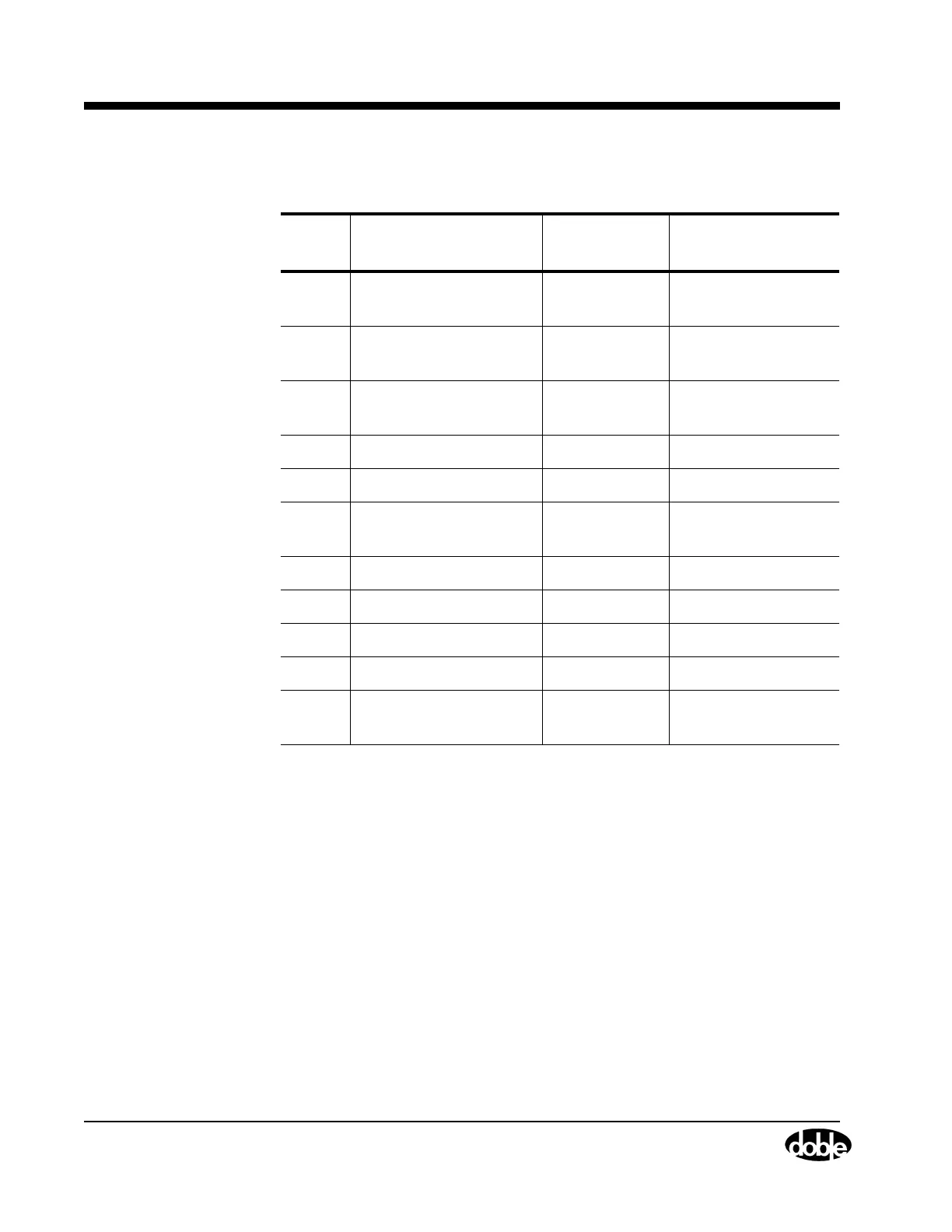
* Connect to an Event module if “Aux Contact” is the trigger source in the
Test Plan, and to the Trigger In receptacles if “Trigger In” is the trigger
source. Table 1.4 applies to a TDR9000 with two Event modules.
Table 1.4 TDR9000
™
Using Recommended Set of Channels
Item Signal Type TDR9000 Module
Connection
1 Main Contact A
(from CT secondary)
Analog Event
2 Main Contact B
(from CT secondary)
Analog Event
3 Main Contact C
(from CT secondary)
Analog Event
4 Trip relay coil current Analog Event
5 DC Supply Voltage Analog Event
6 52X or 52Y relay coil
current
Analog Event
7 52A contact state Aux Contact Event
8 52B contact state Aux Contact Event
9 52X contact state Aux Contact Event
10 52Y contact state Aux Contact Event
11 52CS/T contact state
(for Trigger In source)
Aux Contact Event or Trigger In*