Interruption in Vacuum
A-10 72A-1898 Rev. A 11/01
Monday, November 26, 2001 1:09 pm
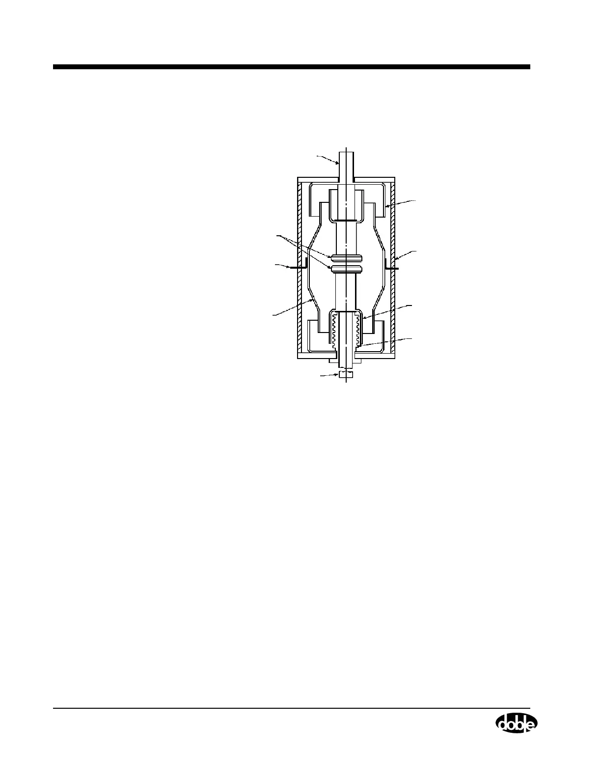
Figure A.9 gives a general vacuum interrupter operational scheme.
(Reprinted from Reference 2. Permission granted by Marcel Dekker, Inc.)
Figure A.9 Vacuum Interrupter Schematic
The ambient gas pressure within the evacuated envelope is 10
−
6
torr.
Under normal circuit conditions the interrupter is closed and contacts
butt together.
Arcing is established within the interrupter by withdrawing the movable
contact from the stationary contact. This arc burns in the metal vapor
evaporated from local hot spots on the contact surfaces. The metal vapor
continually leaves the intercontact region and recondenses on the
contact surfaces and the surrounding metal vapor condensation shield.
The shield is usually isolated from both contacts and serves to protect the
glass or ceramic envelope from vapor deposition. When the current
waveform crosses zero, vapor production ceases and the original
vacuum condition is rapidly approached with the contacts in the open
position. The circuit voltage is withstood internally by the intercontact
gap and externally by the insulating envelope.
Vacuum interrupters are currently applied in 5 through 72.5 kV circuit
breakers.
Flood Terminal
End Shield
Insulating Envelope
Bellows Shield
Bellows
Movable Terminal
Electrodes
Shield Support
Vapor
Flange
Condensation
Shield