Internal Circuit Boards
B-20 72A-1898 Rev. A 11/01
Monday, November 26, 2001 1:09 pm
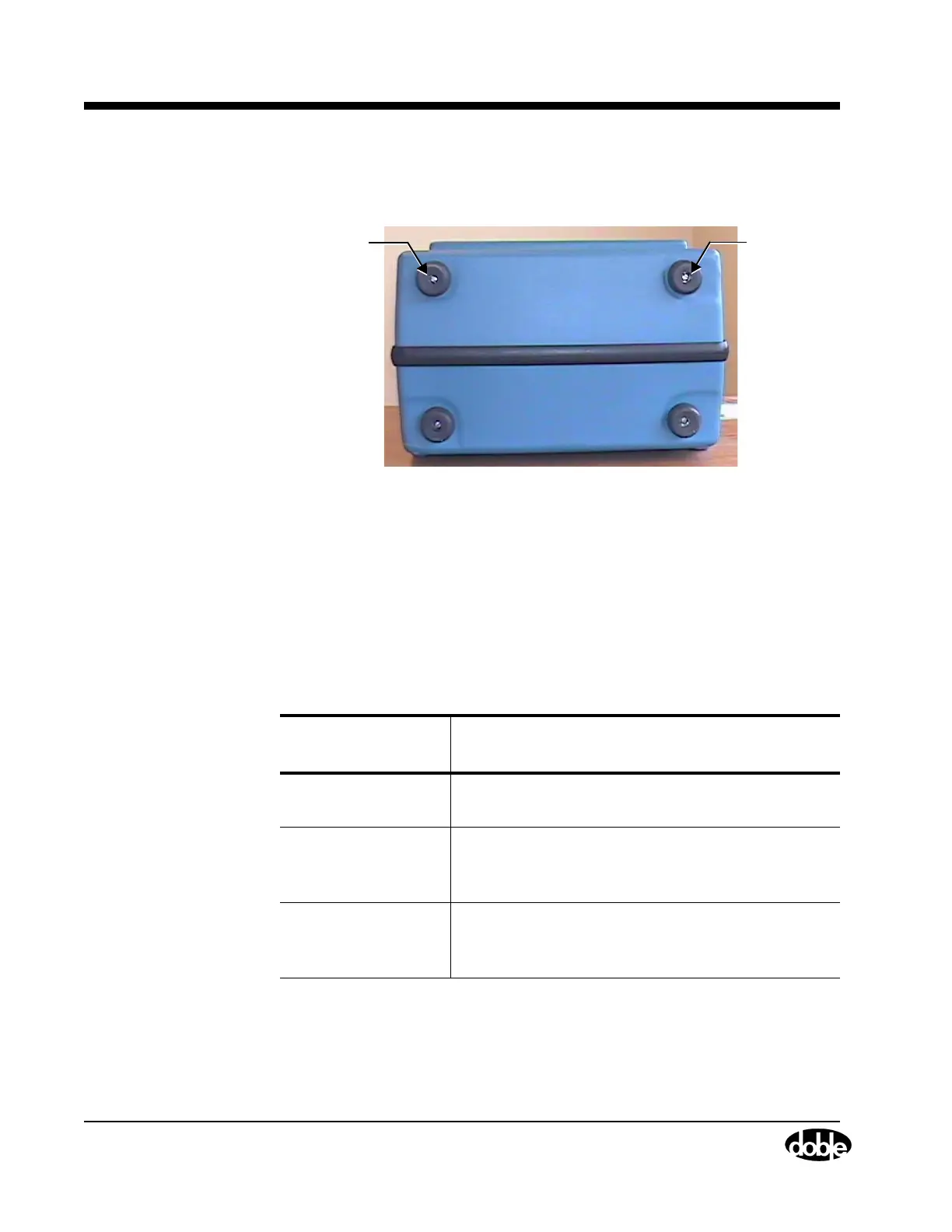
3. Unscrew the two flat head screws that hold the two top rubber feet,
as shown in Figure B.15.
Figure B.15 Screws that Hold Top Rubber Feet
4. Remove the top cover from the Instrument by lifting it up at the back
and sliding it backwards.
5. Disconnect any circuit board ribbon cables required to perform the
replacement.
Table B.2 lists the ribbon cables that need to be disconnected by
circuit board type.
Table B.2 Required Cable Disconnects by Circuit Board
Circuit Board Type
Replaced
Cables for Disconnection
EVG Disconnect the W4 and W3 from the EVG using
the ejectors
CPU Disconnect the W6 from this circuit board using
the two common screws and disconnect the W4
and W3 from the EVG using the ejectors
Trip/Close Disconnect the W4 and the W3 ribbon cables
from the EVG circuit board and the W6 cable
from the CPU board
Screws
for Feet
Screws
for Feet