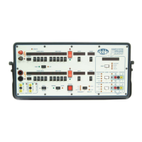
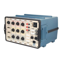
TDR9000
™
Circuit Breaker Test System User’s Guide
72A-1898 Rev. A 11/01 4-31
Monday, November 26, 2001 1:09 pm
To connect the TDR9000:
WARNING When performing connections, always make sure that appropriate
service disconnects are secured and that all safety procedures are
followed. Complete the connection to the TDR9000 Physical Front
Panel first. Connecting cables from a grounded instrument reduces
problems associated with arcing.
1. Remove the front protective cover and store it in a safe place for
reuse.
If the printer option is available, locate the cover/printer assembly
near the laptop.
2. Plug the ground cable into the system ground receptacle and ground
the other end, assuring a secure and reliable connection.
See H in Figure 4.13 on page 4-30.
3. Plug the Safety Switch cable into the SAFETY receptacle of the System
module. If using an external trigger, use the Safety Bypass flag. See N
in Figure 4.13.
4. Ensure that the line voltage is correct (100 - 240 VAC, 50 or
60 cycles).
5. Connect the male end (pin contacts) of the Motion Transducer
cable to one of the three MOTION connectors on the TDR9000
OCB/Motion module (or one of the six, if six channels are available).
See B in Figure 4.13.
6. Connect the female end of the Motion Transducer cable
(socket contacts) to the transducer.
7. Repeat steps 5 and 6 for as many transducers required.
8. Connect one side of the Breaker Control cable to the TRIP/CLOSE
connector on the TDR9000 System module, then connect the other
end of the Breaker Control cable to the circuit breaker.
See I in Figure 4.13.


 To Next Page