39
6-2. Preview Set Up
The switcher does not have a dedicated PREVIEW output. The preview bus output can be
assigned to, however, an auxiliary output. Users can also add the KEY, DSK and PinP images to
PREVIEW. This can be done as explained below:
6-2-1. Preview bus monitoring
Follow the procedure below to assign the preview video to an AUX output. AUX1 is used in
the example below.
(1) Open the [SETUP-OUTPUT-AUX XPT] menu referring to section 6-1. "How to Select Aux
signals."
(2) Turn F1 to select AUX1.
(3) Turn F2 to select PREV.
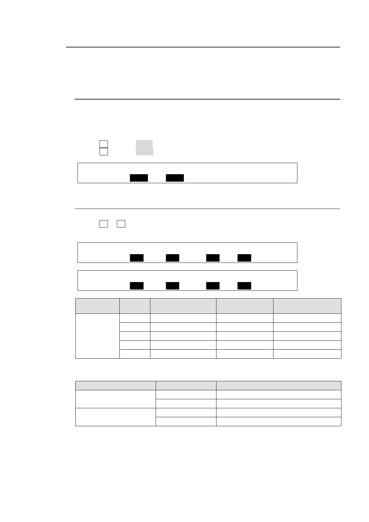
OUTPUT :SELECT : XPT : TRANS RATE : 1/2
AUX XPT : =AUX1 : =PREV : En=OFF =0 :
6-2-2. Setting Up Preview Images
(1) Open PAGE 2 and PAGE 3 in the [SETUP – OUTPUT – CLEAN/PREVIEW] menu.
(2) Turn F1 to F4 to set whether the KEY, DSK and PinP images are to be displayed on the
preview image. Then press the push-button to confirm the setting for each.
OUTPUT : KEY1 : KEY2 : PinP1 : PinP2 : 2/3
PREV OUT: =OFF : =OFF : =OFF : =OFF :
OUTPUT : DSK1 : DSK2 : DSK3 : DSK4 : 3/3
PREV OUT: =OFF : =OFF : =OFF : =OFF :
Item Setting NEXT TRANSITION
KEY
On-Air/Off-Air
KEY image on
PREVIEW
PREVIEW
OUT -
KEY1-2
ON KEY button ON On-Air Not displayed
ON KEY button OFF On-Air Displayed
ON KEY button ON Off-Air Displayed
ON KEY button OFF Off-Air Not displayed
OFF --- --- Not displayed
Whether the KEY images are displayed on the preview depends on both the PREVIEW OUT
settings and KEY button status in the NEXT TRANSITION section.
Item Setting DSK or PinP image on PREVIEW
PREVIEW OUT - DSK1-4
ON Displayed
OFF Not displayed
PREVIEW OUT - PinP1/2
ON Displayed
OFF Not displayed