17
NOTE
See section 16. "Multiviewer" for multi-display connection and setup.
See section 23-1. "GPI Control" and section 23-2-2. "Tally Output Settings (GPI/TALLY
OUT)" for setting up GPI input, GPI output and tally output.
See section 23-2-4. "Sending Tally Signals to Tally Units", if you configure the tally
units (Hanabi series option).
See section 28. "Editor Control (Option)" for editor control.
The HVS-AUX8/16/32 units (Hanabi series option), which are used for selecting AUX
signals, can be deployed in the same Arcnet LAN as HVS-35OU/35ROU. See section
29-1. "ARCNET" for Arcnet connection. See the operation manual of the Auxiliary Unit
for how to connect the AUX units to the switcher.
3-3. How to Connect between MU and OU Units
The multiple control panels (OU) and remote units (RU) can be connected to single HVS-350HS
(MU). The maximum system configuration is:
MU (HVS-350HS) 1
OU (HVS-35OU, HVS-35ROU, HVS-30OU) 3 (Multiple of same model is possible.)
RU (HVS-30RU) 2
MU and OU units communicate via Arcnet. If your MU and OU connection is a one-to-one
connection: an HVS-350HS and HVS-35OU or an HVS-350HS and HVS-35ROU, setup is very
easy. Just connect the MU and OU. Any additional network setting is not necessary.
However, if your HVS-350 series system has two or three OU units, the Arcnet ID of devices
should be changed before configuring the system, because the Arcnet does not work if two
devices with the same ID exist in the network. (The remote control units connect to the MU via
RS-422.)
Model Arcnet ID (default setting)
HVS-35OU 1
HVS-35ROU 1
HVS-350HS 250
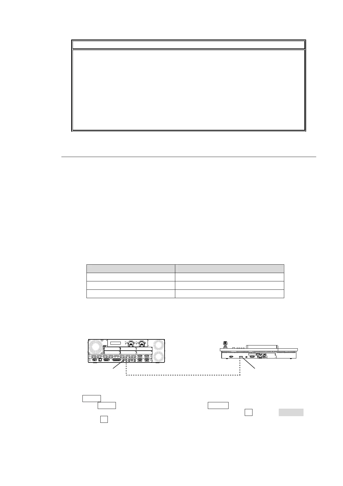
To Change the Arcnet OU ID
(1) Connect the MU (HVS-350HS) and an OU (HVS-35OU or HVS-35RU) via Arcnet using a
BNC cable as shown below.
(2) The MENU control button at the right of the menu display should light up at power ON.
(3) Press the MENU control button and then press the SETUP button.
(4) The SETUP menu's top page appears in the menu display. Turn F1 to select SYSTEM and
then press F1.
RATING LABEL
DB
ECA
OPTION SLOT
F
21
I/O
4
3
2
1
S
D
I
I
N
P
U
T
6
7
8
5
A
U
X
2
R
S
-
4
2
2
1
P
G
M
P
G
M
M
/
E
P
/P
4
1
2
3
5
6
C
P
U
/G
E
N
L
O
C
K
T
O
O
U
G
E
N
L
O
C
K
R
E
F
IN
R
E
F
O
U
T
G
P
I
I
N
E
D
I
T
O
R
G
P
I/
T
A
L
L
Y
O
U
T
4
R
S
-
4
2
2
3
L
A
N
(
1
0
/
1
0
0
B
A
S
E
-
T
)
‚`
‚b
‚P
‚O
‚O
|‚
Q
‚S
‚
O
‚u
@
‚T
‚O
^
‚
U
‚O
‚g
‚š
@
‚h
‚
m
‚`
‚b
‚P
‚O
‚O
|‚Q
‚S
‚O
‚u
@
‚T
‚
O
^
‚U
‚
O
‚g
‚š
@
‚h
‚
m
75Ω terminato
POWER 1 POWER 2
GPI/T AL LY O UT
SER.N O.
HVS-35OU
AC100-240V 50/60Hz IN
RATING LABEL
CONTROL
TO MU
POWER
OFF
ON
(SERVICE)
Arcnet
(75Ω BNC cable)
75Ω terminato
MU ID: 250 OU ID: 1