46
7. Bus Operation
The video signals input to the switcher are assigned to the bus buttons on the control panel for
usage. The assigned signals are shared by the M/E, P/P, and AUX/KEY bus sections.
As a factory default settings, video inputs, Stills and Mattes are assigned to the bus buttons. The
signal assignments are freely changeable. The Button Inhibit function for preventing accidental
button operations is also available. (See section 5-2. "How to Assign Sources to Bus buttons.")
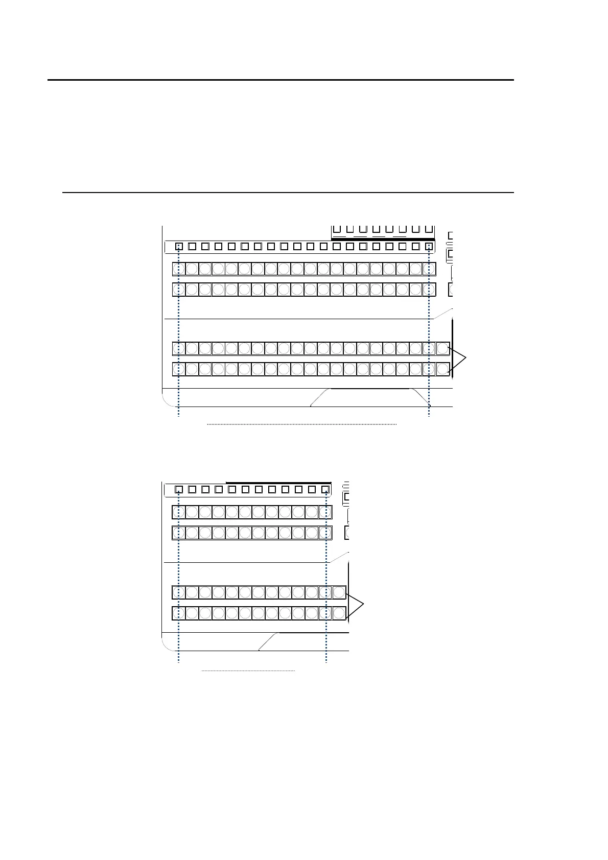
7-1. Selecting Video Sources
HVS-35OU
HVS-35ROU
P/P
121110987654123 M/E
M/E
1110987654123
D
PREV MV1CLEAN MV2
23 45678 91011121
KEY/AUX
PGMPREV CLEANPGM
M/E P/P
13
12
14 15 16 17 18 19 20
13 14 15 16 17 18 19 20
13 14 15 16 17 18 19 20
RE
BKG
KEY/AUX bus
M/E bus
P/P bus
Bus button 1 Bus button 20
M/E re-entry
button
P/P
121110987654123 M/E
M/E
121110987654123
234567891011121
KEY/AUX
RE
BK
DI
KEY/AUX bus
M/E bus
P/P bus
Bus button 1 Bus button 12
M/E re-entry
button