Appendix 3 - 5
No. Name Description Refer to
1 ALARM indicator
Indicates the alarm status in the main unit.
Fan and power alarms for HVS-350HS are indicated.
The indicator blinks red when an alarm occurs. In such
a case, power off the system and consult your FOR-A
supplier. The indicator is normally unlit.
This indicator works the same as the ALARM indicator
located on the front panel of the main unit.
2 Menu Control Block
The menu control block is composed of the menu
display, menu control push-buttons (F1 to F4) and page
up/down buttons.
4
3
MENU
DIRECT PATT
EVENT
KEYPAD
Four mode buttons at the left side change the keypad
mode to the right.
In these modes, the keypad is used for menu access,
transition pattern selection, numeric input and event
control.
4-1-1
4-2-1
8
4 BLACK TRANS Used to perform black transitions.
5 USER BUTTON
User assignable buttons. Menu shortcuts or functions
can be assigned to these buttons.
9
6 USB MEMORY
Used to connect a USB flash memory for image file
import and export or system setting backup.
(USB1.1, Type-A)
7 TRANS PREV
Used to preview next transition.
This button cannot be used with HVS-350HS.
8 BUS SELECT Block
Used to select a bus. Then select a video in the
KEY/AUX bus (No 9).
9 KEY/AUX Bus
Used to select a video signal for the bus selected at the
BUS SELECT block (No.8).
The video signal can be selected from KEY/AUX bus
buttons, PGM, PREV, CLEAN and MV.
10 PGM/PST Bus Used to select video signal for the background. 5-1-1
11 Joystick Block
Used to set position, size or color in the specific menu
parameters.
4-2-2
12 Transition Block Used to perform transitions for background and keyer. 6
13
KEYER/DSK/PINP
Transition Block
Used to perform transitions for KEY, DSK and PINP1/2.
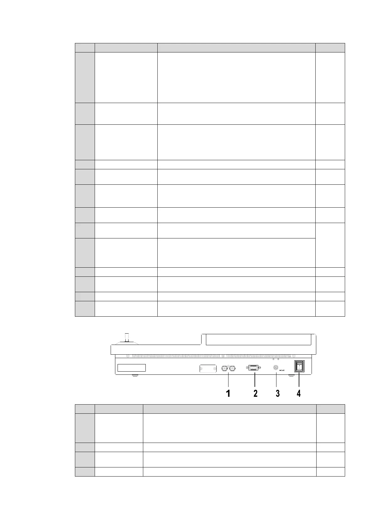
Rear Panel
No. Name Description Refer to
1 TO MU
Arcnet port. Used for the main unit connection.
The other connector (loopthrough) can be used for AUX unit
connection. The loopthrough connector must be 75 ohm
terminated if it is not connected to other system equipment.
10
2 CONTROL Used for service purposes. Do not use.
3 DC 12V IN
Used for DC power connection from the supplied AC
adapter.
4 POWER Used for the unit power On/Off
OFF
POW ER
ON
CONTROL
TO MU
S/No.LABEL
DC12V IN