EasyManuals Logo

GE LOGIQ P5 Service Manual

GE LOGIQ P5
532 pages
To Next Page IconTo Next Page
To Previous Page IconTo Previous Page
Page #120 background imageLoading...
Page #120 background image
GE HEALTHCARE
DIRECTION 5394141, REVISION 5 LOGIQ™ P5 SEVICE MANUAL
4-34 Section 4-8 - Mechanical Function Checks
Section 4-8Mechanical Function Checks
4-8-1 Cover Parts Function Validation
Check if the FRU parts are assembled tightly by naked eye and hands.
Check if there are dents, scratches, or cracks on the FRU parts.
Check if screws are in place.
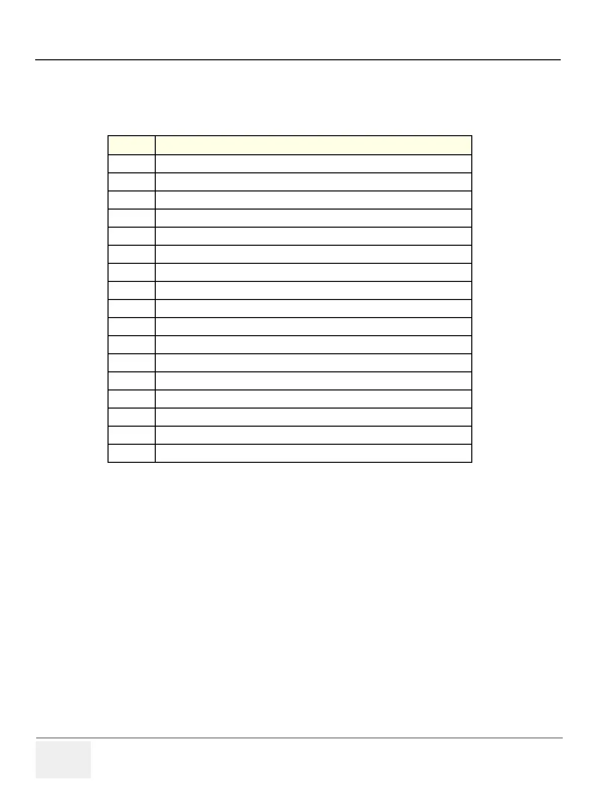
Table 4-10 Cover parts of the FRU
No Item
1
Right and Left cover
2
Front cover
3
Rear cover
4
Middle cover
5
Top cover
6
Top bottom cover
7
Pole cover
8
Neck front cover
9
Neck rear cover
10
Dummy cover L/R
11
EMI cover L/R
12
LCD Std Arm with cover
13
Rear handle
14
Rear hook
15
ECG cable hook
16
Cable Arm hook
17
LP5/LA5 Monitor Cover set

Table of Contents

Other manuals for GE LOGIQ P5

Questions and Answers:

Question and Answer IconNeed help?

Do you have a question about the GE LOGIQ P5 and is the answer not in the manual?

GE LOGIQ P5 Specifications

General IconGeneral
Power Supply100-240VAC, 50/60Hz
Display15" LCD
Doppler ModesColor Doppler, Power Doppler
Imaging ModesB-Mode, M-Mode
ProbesConvex, Linear, Phased Array
ApplicationsAbdominal, Vascular, Cardiac, OB/GYN, Small Parts, Musculoskeletal
ConnectivityDICOM, USB, Ethernet
Probe Connectors3
PortabilityMobile
Operating Temperature10°C to 40°C
Relative Humidity30%

Related product manuals