GE HEALTHCARE
DIRECTION 5394141, REVISION 5 LOGIQ™ P5 SEVICE MANUAL
8-78 Section 8-2 - DISASSEMBLY/RE-ASSEMBLY
8-2-31 Backplane Assy
8-2-31-1 Tools
• Common pilIips screwdrivers
8-2-31-2 Preparations
• Shut down the system and switch off the main breaker.
8-2-31-3 Removal procedure
1.) To detached the backplane, all pwas in the cardcage should be removed from cardcage.
2.) Open the Side Left Cover and Side Right Cover. Refer to the 8-2-15 "Side Left Cover" on page 8-
51 and 8-2-16 "Side Right Cover" on page 8-52.
3.) Open the EMI Cover L and EMI Cover R. Refer to the 8-2-26 "EMI Cover L" on page 8-68 and 8-2-
27 "EMI Cover R" on page 8-69.
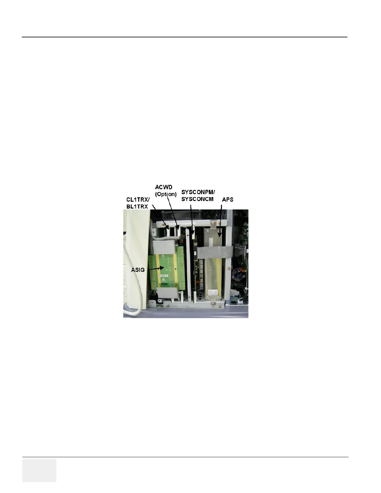
4.) Remove all pwas from the nest box.
5.) Open the front cover. Refer to the 8-2-17 "Front Cover" on page 8-53.
6.) Remove the P3RLY / P2RLY Board. Refer to the 8-2-30 "P3RLY / P2RLY Assy & P2RLY with
Dummy" on page 8-75.
7.) Remove the DVD, HDD. Refer to the 8-2-44 "DVD R/W Drive" on page 8-98 and 8-2-47 "SATA HDD
Assy" on page 8-104.
8.) Unplug all the cable connectors all in Backplane Assy.
Figure 8-113 PWAs in the nest box
 Loading...


