GE HEALTHCARE
DIRECTION 5394141, REVISION 5 LOGIQ™ P5 SEVICE MANUAL
8-74 Section 8-2 - DISASSEMBLY/RE-ASSEMBLY
8-2-29 CL1TRX Assy / BL1TRX Assy
8-2-29-1 Tools
• Common pilIips screwdrivers
8-2-29-2 Preparations
• Shut down the system and switch off the main breaker.
8-2-29-3 Removal procedure
1.) Remove the Side Right Cover. Refer to the 8-2-16 "Side Right Cover" on page 8-52.
2.) Remove the EMI Cover R. Refer to the 8-2-27 "EMI Cover R" on page 8-69.
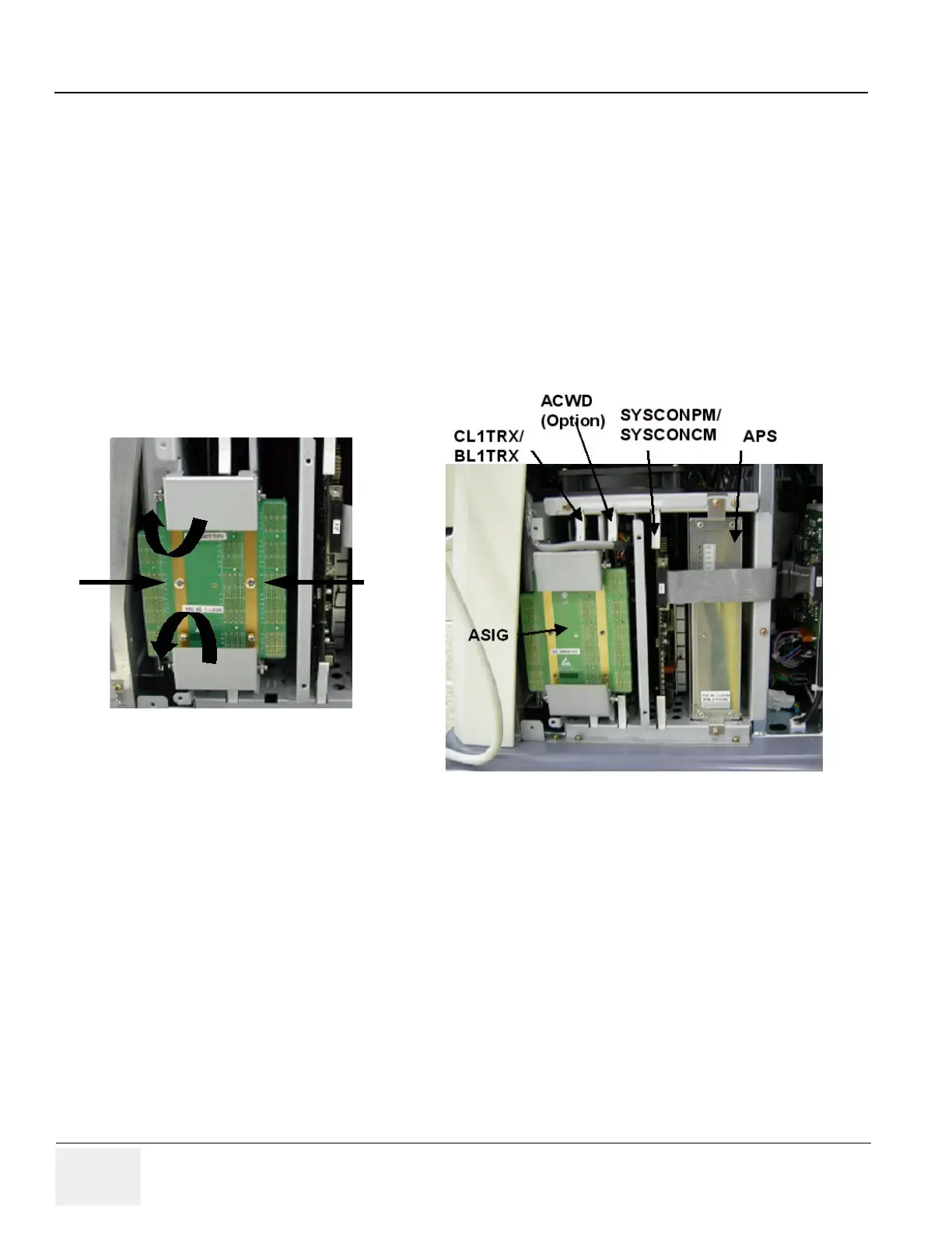
3.) Unscrew 2 screws (1-2) and eject the PCB.
4.) The CL1TRX(BL1TRX) board is located on the most left slot in the nest box.
Figure 8-109 Eject ASIG Assy
 Loading...


