EasyManuals Logo

GE LOGIQ P5 Service Manual

GE LOGIQ P5
532 pages
To Next Page IconTo Next Page
To Previous Page IconTo Previous Page
Page #340 background imageLoading...
Page #340 background image
GE HEALTHCARE
DIRECTION 5394141, REVISION 5 LOGIQ™ P5 SEVICE MANUAL
8-94 Section 8-2 - DISASSEMBLY/RE-ASSEMBLY
8-2-39 Rear Hook
8-2-39-1 Tools
Common pilIips screwdrivers
8-2-39-2 Preparations
Shut down the system and switch off the main breaker.
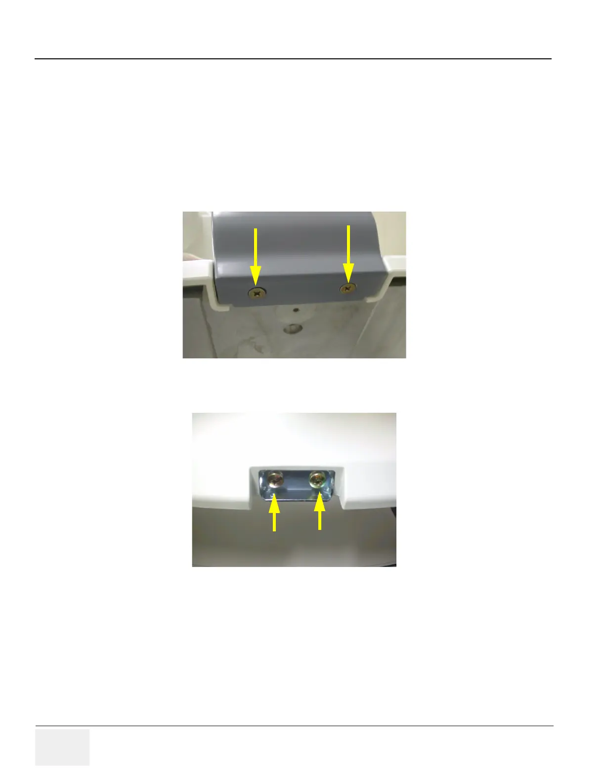
8-2-39-3 Removal procedure
1.) Unscrew 2 screws (1-2) and remove Rear hook.
2.) Unscrew 2 screws (1-2) and remove.
Figure 8-128 Screws on rear hook
Figure 8-129 Screws on the rear hook fix brkt

Table of Contents

Other manuals for GE LOGIQ P5

Questions and Answers:

Question and Answer IconNeed help?

Do you have a question about the GE LOGIQ P5 and is the answer not in the manual?

GE LOGIQ P5 Specifications

General IconGeneral
Power Supply100-240VAC, 50/60Hz
Display15" LCD
Doppler ModesColor Doppler, Power Doppler
Imaging ModesB-Mode, M-Mode
ProbesConvex, Linear, Phased Array
ApplicationsAbdominal, Vascular, Cardiac, OB/GYN, Small Parts, Musculoskeletal
ConnectivityDICOM, USB, Ethernet
Probe Connectors3
PortabilityMobile
Operating Temperature10°C to 40°C
Relative Humidity30%

Related product manuals