GE HEALTHCARE
DIRECTION 5394141, REVISION 5 LOGIQ™ P5 SEVICE MANUAL
Section 8-2 - DISASSEMBLY/RE-ASSEMBLY 8-71
8-2-28 APS/APS Pro Assy
NOTE: APS Power Supply can not be adjusted.
8-2-28-1 Tools
• Common pilIips screwdrivers
•Nipper
8-2-28-2 Preparations
• Shut down the system and switch off the main breaker.
8-2-28-3 Removal procedure
1.) Remove the Side Left Cover. Refer to the 8-2-15 "Side Left Cover" on page 8-51.
2.) Remove the EMI Cover L. Refer to the 8-2-26 "EMI Cover L" on page 8-68.
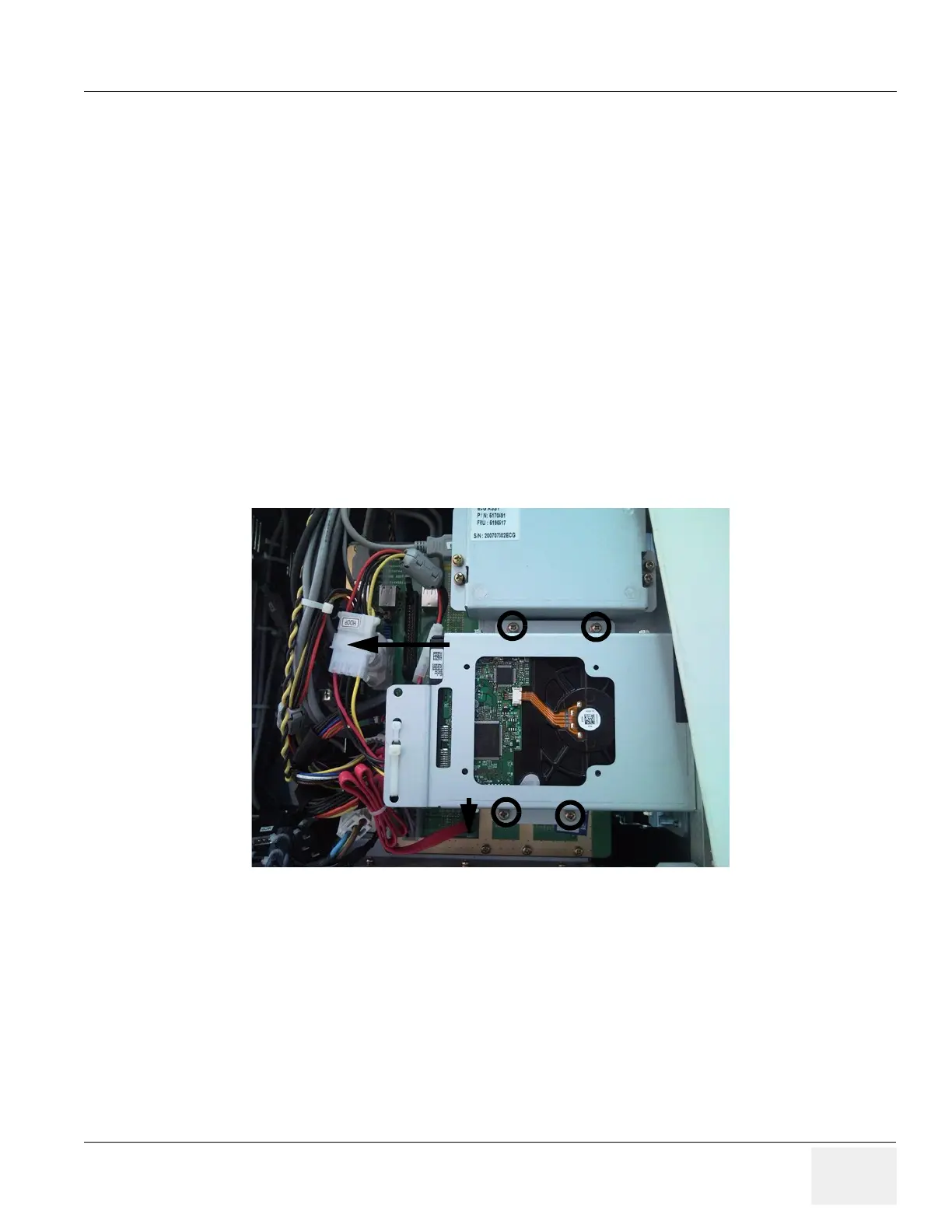
3.) Remove Hard Disk assy to unplug the APS/APS Pro connectors on backplane easily.
- Unplug the HDD power connector on the HDD and the SATA connector from the bottom side
of the backplane. Pull out the connector.
4.) Unscrew 4 screws of the HDD bracket.
5.) Unplug the DC power connector from DVD RW drive.
6.) The APS/APS Pro assy have 5 connectors, 3 connectors are pluged on backplane and 1 connector
is connected to nest cooling fan power and 1 connector is AC power connector.
Figure 8-106 Remove HDD
HDD Connector
SATA Connector

 Loading...


