EasyManuals Logo

GE LOGIQ P5 Service Manual

GE LOGIQ P5
532 pages
To Next Page IconTo Next Page
To Previous Page IconTo Previous Page
Page #350 background imageLoading...
Page #350 background image
GE HEALTHCARE
DIRECTION 5394141, REVISION 5 LOGIQ™ P5 SEVICE MANUAL
8-104 Section 8-2 - DISASSEMBLY/RE-ASSEMBLY
8-2-46 ARP Assy 110V/220V
8-2-46-1 Tools
Common pilIips screwdrivers
8-2-46-2 Preparations
Shut down the system and switch off the main breaker.
8-2-46-3 Removal procedure
1.) Remove side right cover and EMI cover. Refer to the 8-2-16 "Side Right Cover" on page 8-52 and
8-2-27 "EMI Cover R" on page 8-69.
2.) Remove the Rear Cover. Refer to the 8-2-18 "Rear Cover" on page 8-55.
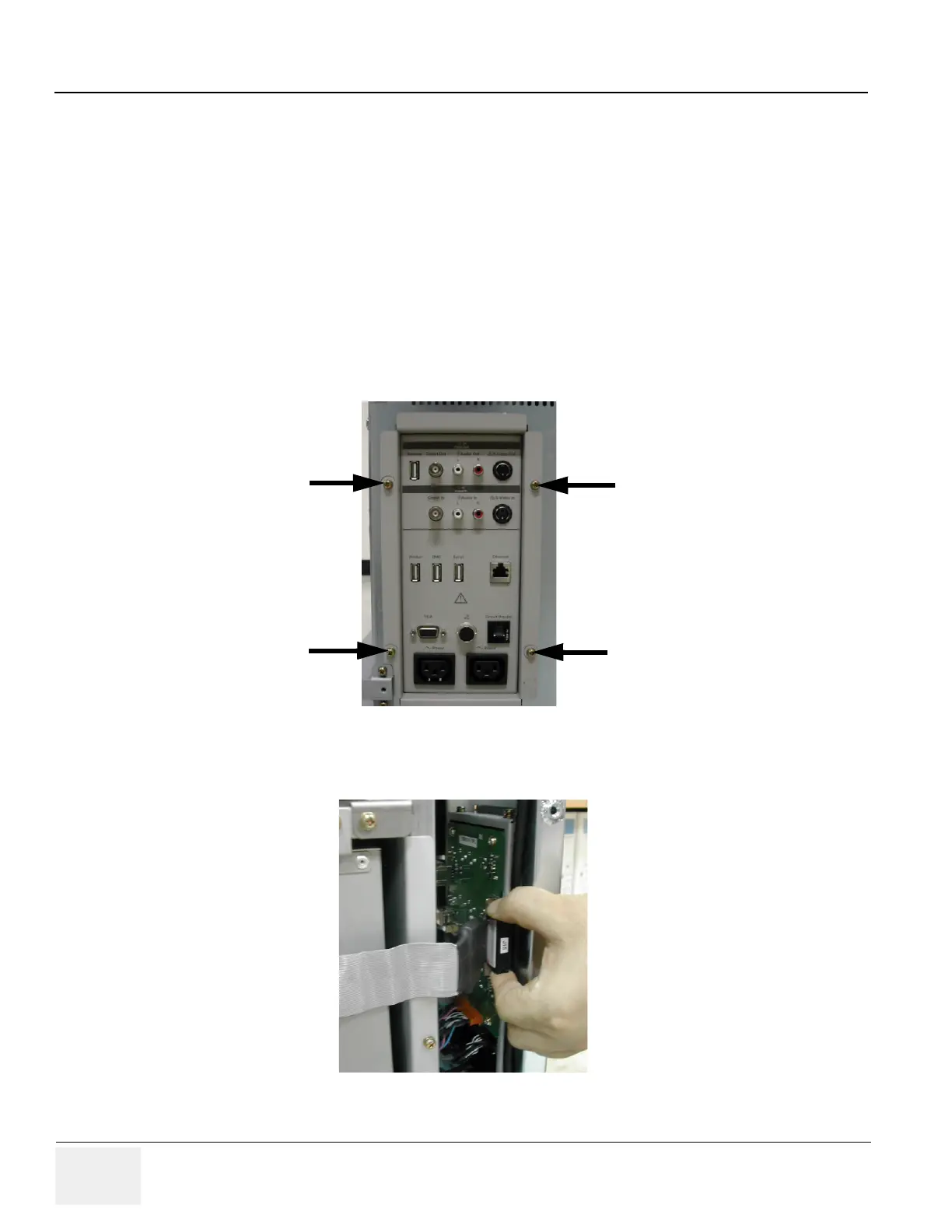
3.) Unscrew 4 screws (1-4).
4.) Disconnect J15 connector.
Figure 8-140 Screws of the rear panel
Figure 8-141 AEXP Cable of rear panel
(1)
(3)
(4)
(2)

Table of Contents

Other manuals for GE LOGIQ P5

Questions and Answers:

Question and Answer IconNeed help?

Do you have a question about the GE LOGIQ P5 and is the answer not in the manual?

GE LOGIQ P5 Specifications

General IconGeneral
Power Supply100-240VAC, 50/60Hz
Display15" LCD
Doppler ModesColor Doppler, Power Doppler
Imaging ModesB-Mode, M-Mode
ProbesConvex, Linear, Phased Array
ApplicationsAbdominal, Vascular, Cardiac, OB/GYN, Small Parts, Musculoskeletal
ConnectivityDICOM, USB, Ethernet
Probe Connectors3
PortabilityMobile
Operating Temperature10°C to 40°C
Relative Humidity30%

Related product manuals