EasyManuals Logo

GE LOGIQ P5 Service Manual

GE LOGIQ P5
532 pages
To Next Page IconTo Next Page
To Previous Page IconTo Previous Page
Page #141 background imageLoading...
Page #141 background image
GE HEALTHCARE
DIRECTION 5394141, REVISION 5 LOGIQ™ P5 SEVICE MANUAL
Section 5-1 - Overview 5-1
Chapter 5
Components and Functions (Theory)
Section 5-1
Overview
5-1-1 Purpose of Chapter 5
This chapter explains system concepts, component arrangement, and subsystem function of LOGIQ™
P5 and LOGIQ™ A5. It also describes the Power Distribution System (PDS) and probes.
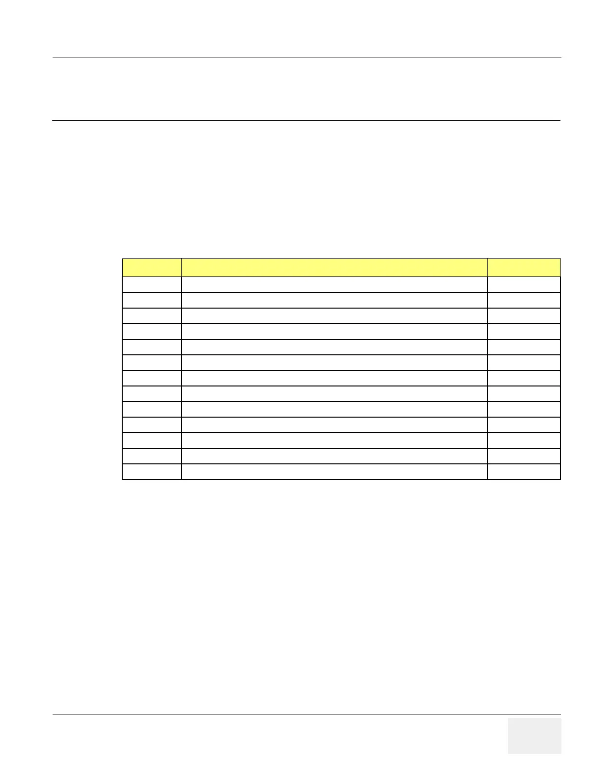
Table 5-1 Contents in Chapter 5
Section Description Page Number
5-1 Overview 5-1
5-2 General Information 5-2
5-3 Block Diagram 5-3
5-4 Main Board Detail 5-9
5-5 Top Console 5-26
5-6 ARP (Rear Panel) 5-30
5-7 Power Diagrams 5-32
5-8 Cable Connection 5-35
5-9 Filters 5-39
5-10 Service Platform 5-40
5-11 RFS (Service For Request) 5-52
5-12 Machine RFS 5-56
5-13 Fast Polling 5-59

Table of Contents

Other manuals for GE LOGIQ P5

Questions and Answers:

Question and Answer IconNeed help?

Do you have a question about the GE LOGIQ P5 and is the answer not in the manual?

GE LOGIQ P5 Specifications

General IconGeneral
Power Supply100-240VAC, 50/60Hz
Display15" LCD
Doppler ModesColor Doppler, Power Doppler
Imaging ModesB-Mode, M-Mode
ProbesConvex, Linear, Phased Array
ApplicationsAbdominal, Vascular, Cardiac, OB/GYN, Small Parts, Musculoskeletal
ConnectivityDICOM, USB, Ethernet
Probe Connectors3
PortabilityMobile
Operating Temperature10°C to 40°C
Relative Humidity30%

Related product manuals