GE HEALTHCARE
DIRECTION 5394141, REVISION 5 LOGIQ™ P5 SEVICE MANUAL
8-50 Section 8-2 - DISASSEMBLY/RE-ASSEMBLY
8-2-14 Keycap set, Main Keyboard Encoder Knob set
8-2-14-1 Tools
• Common pilIips screwdrivers
8-2-14-2 Preparations
• Shut down the system and switch off the main breaker.
8-2-14-3 Removal procedure
1.) Remove key caps from the keyboard.
2.) Perform the following functional tests. If all are successful, include the debrief script provided below.
8-2-14-4 Mounting Procedure
Install the new parts in the reverse order of removal.
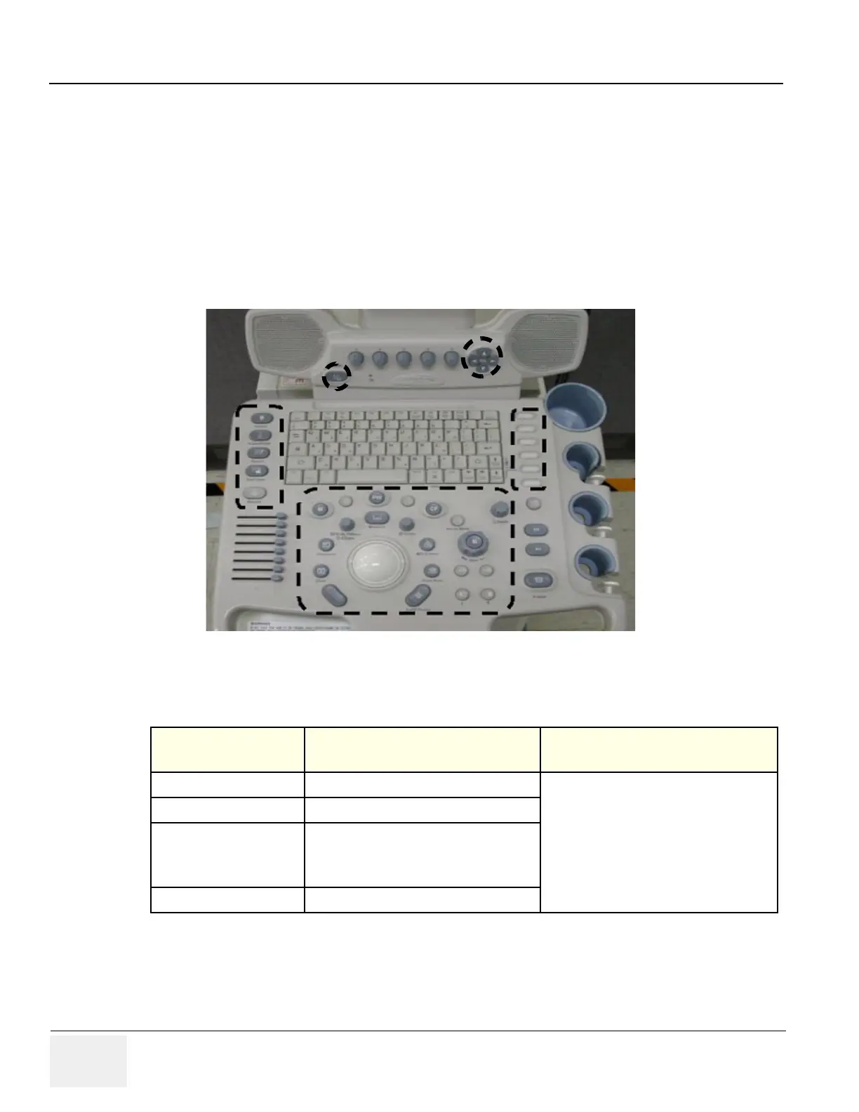
Figure 8-83 Key Caps
Table 8-15 Functional Tests
Service Manual
Section
Functional Test / Diagnostic Test Debrief Script
Section 4-3-1
Power On/Boot Up
“Service Manual, Direction
5394141, Rev 1+, Section 8-2-14. Equipment
passed all required tests and is ready for use. “
Section 4-3-2
Power Off / Shutdown
Section 4-8-4
TGC key assy/TGC Knob Set, Sub keyboard
encoder Knob Set, Keycap set, Main Keyboard
Encoder Knob set Function Validation
Procedure
Section 10-5-5
Physical Inspection

 Loading...


