GE HEALTHCARE
DIRECTION 5394141, REVISION 5 LOGIQ™ P5 SEVICE MANUAL
Section 8-2 - DISASSEMBLY/RE-ASSEMBLY 8-111
8-2-49 Transbox Assy 110V/220V
8-2-49-1 Tools
• Common pilIips screwdrivers
• Allen/Unbraco wrench
8-2-49-2 Preparations
• Shut down the system and switch off the main breaker.
8-2-49-3 Removal procedure
• To detached the AC Power assy, All open 4 pcs console cover that are left, right, front, rear cover
1.) Remove side left cover and right side cover. Refer to the 8-2-15 "Side Left Cover" on page 8-51 and
8-2-16 "Side Right Cover" on page 8-52.
2.) Remove rear side cover and front cover. Refer to the 8-2-17 "Front Cover" on page 8-53 and 8-2-
18 "Rear Cover" on page 8-55.
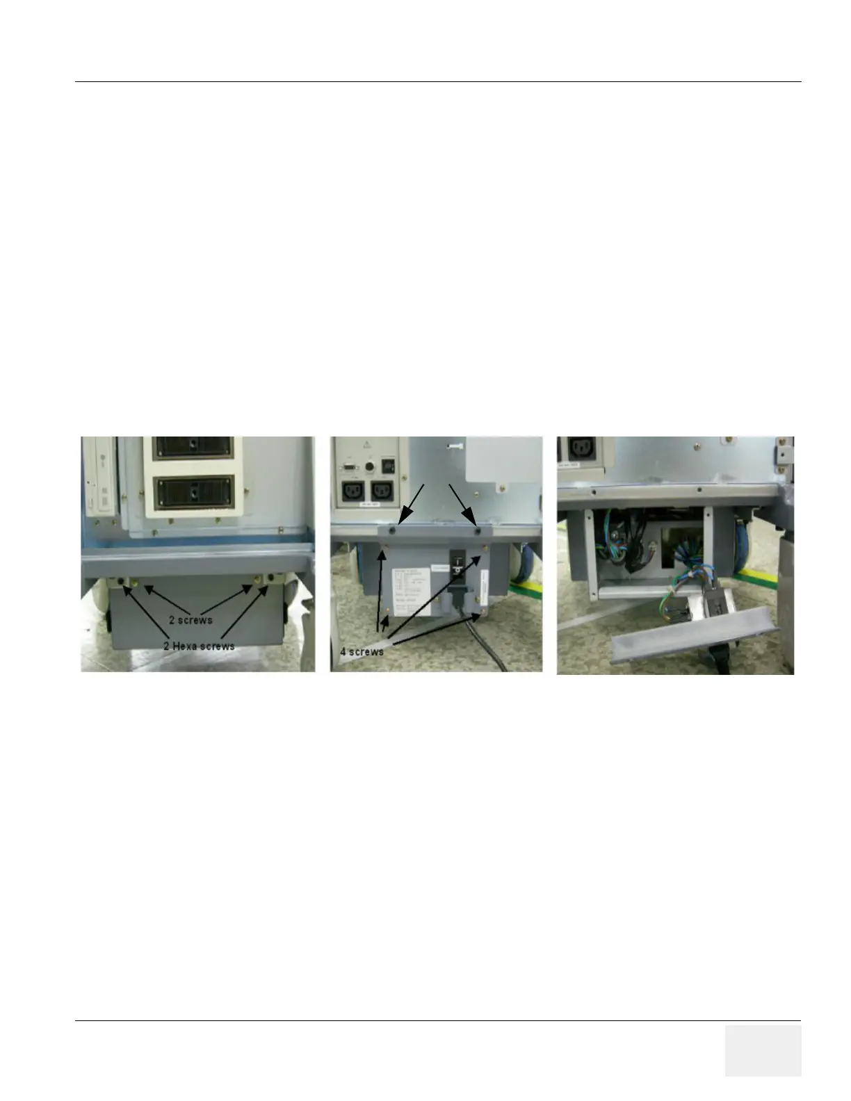
3.) Unscrew 2 pcs M4 screw and 2 pcs hexa screw on the front of AC trans box. And unscrew 4 pcs
screw and 2pcs hexa screw on the rear side of Transbox assy and open inlet panel.
4.) Unplug 4 connectors inside of AC transbox and pull out the transbox assy.
5.) Pull out the transbox assy.
Figure 8-148 4 screw on the front of the AC transbox assy

 Loading...


