GE HEALTHCARE
DIRECTION 5394141, REVISION 5 LOGIQ™ P5 SEVICE MANUAL
Section 5-4 - Main Board Detail 5-11
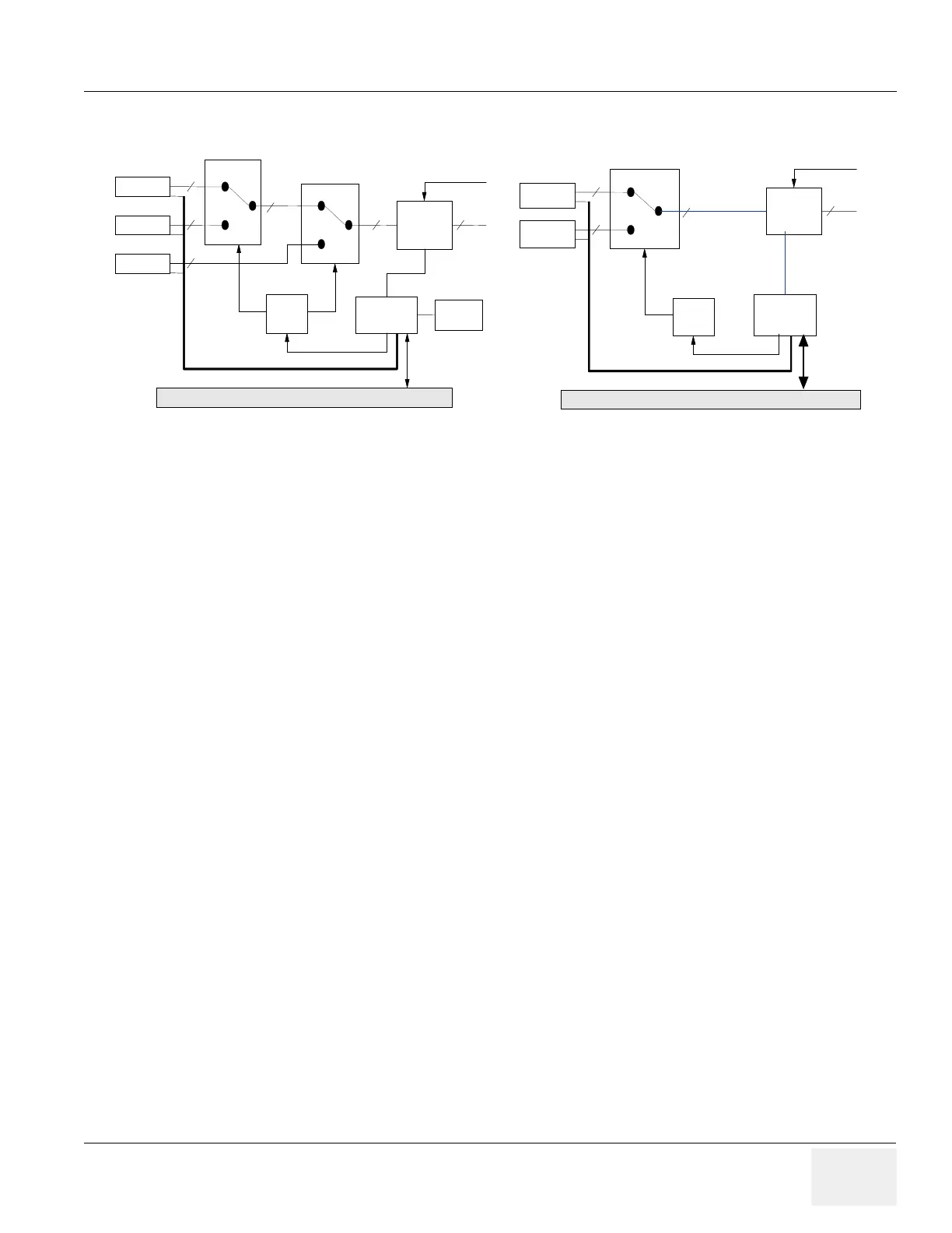
5-4-1 P3RLY and P2RLY
P3RLY ASSY contains of 3 probe connectors and provides switchable connection between probes and
64ch transmitters/receivers. P2RLY contains 2 probe connector
The main function of P3RLY ASSY and P2RLY ASSY is as follows.
- 3-to-1 selectors with three probe ports for P3RLY board.
- 2 to 1 selector with two probe ports for P2RLY board
- Interface with FEBUS (control bus)
- Supply/Cut control and failure detection of supply voltage for Mux circuit in a Probe.
- Device: Mechanical Relay.
5-4-1-1 Interface to Probe
• Probe Status detection
- Detects whether or not a probe is connected.(POPEN)
- Detects ID code of a connected probe.(PCODE)
• Mux Interface
- Transfers control data of Mux to a probe.(CONSYS,CONSTA)
- Enables/Disables control of data.
- Detects whether Mux data setting is finished or not.
• Power Supply for Mux
- Supply/Cut control:
+5V and +12V on a connector are supplied while a probe is connected to the connector.
+/-SHV are supplied only while a probe is selected.
• LED Blinking
- The LED in a probe blinks when the probe is selected.
Figure 5-10 P3RLY & P2RLY Block Diagram
PORT A
PORT B
RELAY
HV MUX
Control
Circuit
Control
FPGA
Probe ID Interface
128
128
128
To CL1TRX
SHV
FEBUS
64
PORT A
PORT B
RELAY
HV MUX
Control
Circuit
Control
FPGA
Probe ID Interface
128
128
128
To CL1TRX
SHV
FEBUS
64
PORT A
PORT B
PORT C
RELAY
RELAY
HV MUX
Control
Circuit
Control
FPGA
Temperature
Sensor
Probe ID Interface
128
128
128
128
128
To CL1TRX
SHV
FEBUS
64
PORT A
PORT B
PORT C
RELAY
RELAY
HV MUX
Control
Circuit
Control
FPGA
Temperature
Sensor
Probe ID Interface
128
128
128
128
128
To CL1TRX
SHV
FEBUS
64