EasyManuals Logo

GE LOGIQ P5 Service Manual

GE LOGIQ P5
532 pages
To Next Page IconTo Next Page
To Previous Page IconTo Previous Page
Page #332 background imageLoading...
Page #332 background image
GE HEALTHCARE
DIRECTION 5394141, REVISION 5 LOGIQ™ P5 SEVICE MANUAL
8-86 Section 8-2 - DISASSEMBLY/RE-ASSEMBLY
8-2-34 PM SOM Assy with 1G/ CM SOM Assy with 512M
8-2-34-1 Tools
Common pilIips screwdrivers
8-2-34-2 Preparations
Shut down the system and switch off the main breaker.
8-2-34-3 Removal procedure
1.) Remove the Side Right Cover. Refer to the 8-2-16 "Side Right Cover" on page 8-52.
2.) Remove the EMI Cover R. Refer to the 8-2-27 "EMI Cover R" on page 8-69.
3.) Remove the SYSCOM PM / CM Assy. Refer to the 8-2-33 "SYSCON PM Assy/SYSCON CM Assy"
on page 8-81.
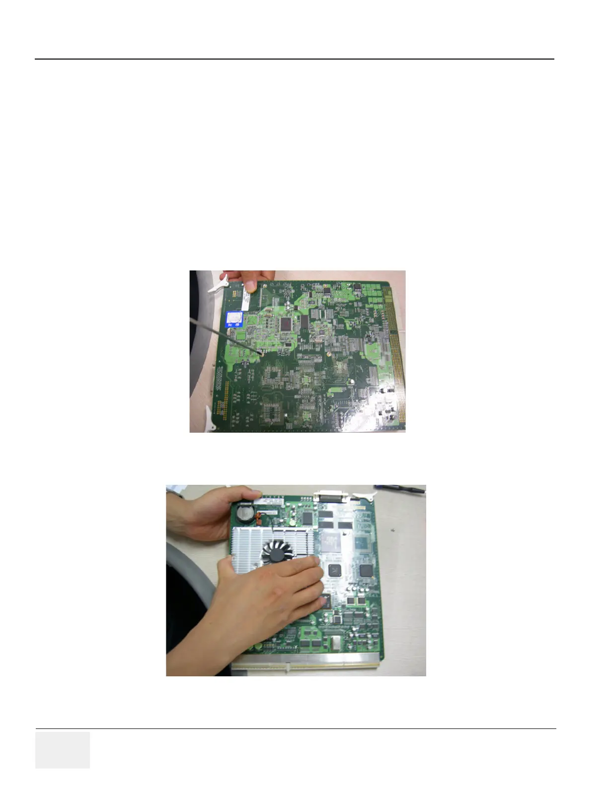
4.) Unscrews 4 screws.
5.) Remove the SOM Assy.
Figure 8-120 4 screws for SOM on SYSCON
Figure 8-121 Detached the SOM from SYSCON PWA

Table of Contents

Other manuals for GE LOGIQ P5

Questions and Answers:

Question and Answer IconNeed help?

Do you have a question about the GE LOGIQ P5 and is the answer not in the manual?

GE LOGIQ P5 Specifications

General IconGeneral
Power Supply100-240VAC, 50/60Hz
Display15" LCD
Doppler ModesColor Doppler, Power Doppler
Imaging ModesB-Mode, M-Mode
ProbesConvex, Linear, Phased Array
ApplicationsAbdominal, Vascular, Cardiac, OB/GYN, Small Parts, Musculoskeletal
ConnectivityDICOM, USB, Ethernet
Probe Connectors3
PortabilityMobile
Operating Temperature10°C to 40°C
Relative Humidity30%

Related product manuals