GE HEALTHCARE
DIRECTION 5394141, REVISION 5 LOGIQ™ P5 SEVICE MANUAL
10-14 Section 10-6 - Electrical Safety Tests
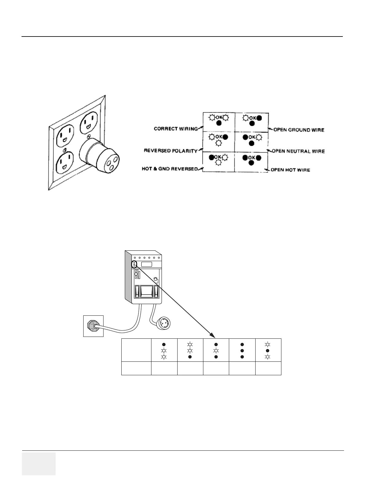
10-6-3 Outlet Test - Wiring Arrangement - USA & Canada
Test all outlets in the area for proper grounding and wiring arrangement by plugging in the neon outlet
tester and noting the combination of lights that are illuminated. Any problems found should be reported
to the hospital immediately and the receptacle should not be used.
The Dale 600 has self-contained lamps designed for testing the outlet wiring arrangement. Plug the
Dale 600 into each outlet to be tested comparing the lamp status.
NOTE: No outlet tester can detect the condition where the Neutral (grounded supply) conductor and the
Grounding (protective earth) conductor are reversed. If later tests indicate high leakage currents, this
should be suspected as a possible cause and the outlet wiring should be visually inspected.
Figure 10-1 Typical Outlet Tester
Figure 10-2 Dale 600 Outlet Test
Combination
of
Lights
Condition
CORRECT
WIRING
REVERSE
POLARITY
OPEN
GROUND
OPEN
HOT
HOT/GROUND
REVERSED
 Loading...


