EasyManuals Logo

GE LOGIQ P5 Service Manual

GE LOGIQ P5
532 pages
To Next Page IconTo Next Page
To Previous Page IconTo Previous Page
Page #430 background imageLoading...
Page #430 background image
GE HEALTHCARE
DIRECTION 5394141, REVISION 5 LOGIQ™ P5 SEVICE MANUAL
8-184 Section 8-7 - Mechanical Option Installation instruction
8-7-5 Cable Arm Hook installation
1.) Cable Arm Hook should be installed in prior to installing Probe Cable Hanger, or Endo Probe
Holder.
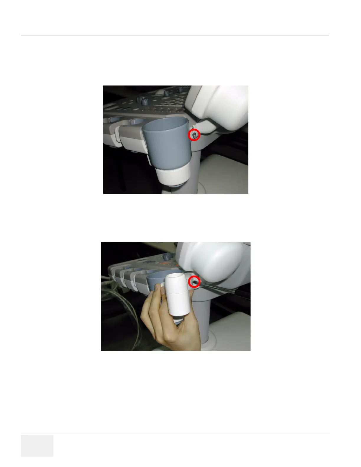
2.) Unscrew 1 existing screw(2159634, BH M4x10 WHT) from the rear side of the keyboard.
3.) Screw 2 screws(2306565 BH M4x16 WHT, 2159634 BH M4x10 WHT) to fix the Cable Arm hook.
User longer screw provide on the upper hole, and use existing screw removed in the step 2 on the
figure below.
Figure 8-256 Cable Arm Hook installation
Figure 8-257 Cable Arm Hook installation

Table of Contents

Other manuals for GE LOGIQ P5

Questions and Answers:

Question and Answer IconNeed help?

Do you have a question about the GE LOGIQ P5 and is the answer not in the manual?

GE LOGIQ P5 Specifications

General IconGeneral
Power Supply100-240VAC, 50/60Hz
Display15" LCD
Doppler ModesColor Doppler, Power Doppler
Imaging ModesB-Mode, M-Mode
ProbesConvex, Linear, Phased Array
ApplicationsAbdominal, Vascular, Cardiac, OB/GYN, Small Parts, Musculoskeletal
ConnectivityDICOM, USB, Ethernet
Probe Connectors3
PortabilityMobile
Operating Temperature10°C to 40°C
Relative Humidity30%

Related product manuals